
Laptop User Manual

CPCI-6020 CompactPCI Single Board Computer Installation and Use (6806800A51C)
Transition Module Preparation and Installation Installing the PIM
138
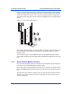
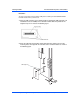
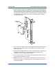
3. Gently press the top of the SIM to seat it on the transition module SIM connector. If
the SIM does not seat with gentle pressure, recheck the alignment of the
connectors. Do not force the SIM onto the transition module.
4. Secure the SIM to the transition module standoffs with the two Phillips-head screws
provided. Do not over tighten the screws.
7.6 Installing the PIM
If a PIM has already been installed on the CPCI-6020-MCPTM-01, or you are installing a
transition module as it has been shipped from the factory, disregard this section and proceed
to Installing and Removing the Transition Module.
Procedure
For PIM installation, perform the following steps:
1. Attach an ESD strap to your wrist. Attach the other end of the ESD strap to the
chassis as a ground. The ESD strap must be secured to your wrist and to ground
throughout the procedure.
2. Perform an operating system shutdown. Turn the AC or DC power off and remove
the AC cord or DC power lines from the system.
3. Remove chassis or system cover(s) as necessary for access to the CompactPCI.
4. Carefully remove the transition module from its CompactPCI card slot and lay it flat
on a stable surface.
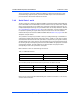
5. Remove the PIM filler from the front panel of the transition module.
Product Damage
Inserting or removing modules in a non-hot swap chassis with the power applied may
result in damage to the module components. The CPCI-6020-MCPTM-01 is not a hot
swap board, but it may be installed in a hot swap chassis with power applied if the
corresponding CPCI-6020 is removed from the front slot first.
Personal Injury or Death
Dangerous voltages, capable of causing death, are present in this equipment.
Use extreme caution when handling, testing and adjusting.