
Laptop User Manual


PMC 66 Mhz Disable Jumper Controls, LEDs, and Connectors
CPCI-6020 CompactPCI Single Board Computer Installation and Use (6806800A51C)
73
3.4.8 PMC 66 Mhz Disable Jumper
A 0.1 inch, 2-pin header (J21) located on the CPCI-6020 disables 66 MHz operation on PCI Bus
B if jumpered. When a jumper is installed between pins 1 and 2, the PCI Bus B operates at
33MHz, regardless of the PMC’s capability. This jumper setting prevents the secondary
Ethernet controller from being disabled if a 66 MHz capable PMC is installed. The jumper pulls
the M66EN signal low so the PMC knows the bus is running at 33 MHz.
3.4.9 Remote Switch Connector
A 0.1 inch, 3-pin header (J19) located on the CPCI-6020 can be used to extend the front panel's
Reset and Abort switches functions through the cables to a remote location.
3.4.10 Flash Write Protect Enable Jumper
A 0.1 inch, 2-pin header (J20) located on the CPCI-6020 enables write protect of bank A flash.
When a jumper is installed between pins 1 and 2, the flash cannot be written.
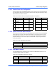
Table 3-19 J21 PMC 66 MHz Disable Jumper
Pin Signal
1GND
2 M66EN
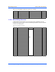
Table 3-20 J19 Remote Switch Connector
Pin Signal
1 Abort
2 GND
3 Reset
Table 3-21 J20 Flash Write Protect Enable Jumper
Pin Signal
1 VPP
2 GND