
Specifications


Specifications A-7
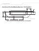
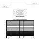
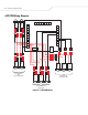
Sensor and Light PCB Signals and Pinouts
Figure A-5. PCB Diagram
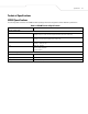
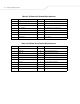
Table A-2. J4 Pinout: 12-Pin Terminal Block Connector
Pin Number Pin Name Direction Description
1 LEFT_MOTION_SENSOR_PWR - 24 VDC to power left motion sensor
2 LEFT_MOTION_SENSOR_NO I Left motion sensor input signal
3 LEFT_MOTION_SENSOR_COM - Left motion sensor common
4 RIGHT_MOTION_SENSOR_NO I Right motion sensor input signal
5 RIGHT_MOTION_SENSOR_COM - Right motion sensor common
6 RIGHT_MOTION_SENSOR_PWR - 24 VDC to power right motion sensor
7 SPARE_PWR - 24 VDC spare power
8 SPARE_COM O Spare common
9 SPARE_GND - Spare ground
10 CHASSIS_GRN - Chassis green LED cathode
11 CHASSIS_COM - Chassis red and green LED anode
12 CHASSIS_RED O Chassis red LED cathode