CAUTION RISK OF ELECTRIC SHOCK CAUTION: TO REDUCE THE RISK OF ELECTRIC SHOCK, DO NOT REMOVE COVER (OR BACK). NO USER-SERVICEABLE PARTS INSIDE. REFER SERVICING TO QUALIFIED SERVICE PERSONNEL. Graphical symbols and supplemental warning marking locations on bottom of terminal. WARNING TO PREVENT FIRE OR SHOCK HAZARD, DO NOT EXPOSE THIS APPLIANCE TO RAIN OR MOISTURE.
IMPORTANT SAFEGUARDS Read instructions All the safety and operating instructions should be read before the appliance is operated. Retain instructions The safety and operating instructions should be retained for future reference. Heed warnings All warnings on the appliance and in the operating instructions should be adhered to. Follow instructions All operating and use instructions should be followed. Cleaning Unplug this product from the wall outlet before cleaning.
IMPORTANT SAFEGUARDS Alternate warnings This equipment may be equipped with a 3-wire grounding-type plug, a plug having a third (grounding) pin. This pin will only fit into a grounding-type power outlet. This is a safety feature. If you are unable to insert the plug into the outlet, contact your electrician to replace your obsolete outlet. Do not defeat the safety purpose of the grounding-type plug.
IMPORTANT SAFEGUARDS Safety check Upon completion of any service or repairs to this video product, ask the service technician to perform safety checks to determine that the product is in proper operational condition. Telephone equipment Observe the following precautions when installing telephone modem equipment: a Never install telephone wiring during a lightning storm. b Never install telephone jacks in a wet location unless the jack is specifically designed for wet locations.
Canadian Compliance This Class B digital apparatus meets all requirements of the Canadian Interference-Causing Equipment Regulations. Cet appareil numérique de la classe B respects toutes les exigences du Règlement sur le matériel brouilleur du Canada. NOTE This product was FCC approved under test conditions that included the use of the supplied cable between system components. To be in compliance with FCC regulation, the user must use this cable and install it properly.
___________________________________________________________________________________ Copyright © 2001 by Motorola, Inc. All rights reserved. No part of the contents of this book may be reproduced or transmitted in any form or by any means without written permission of the publisher. MOTOROLA and the stylized M logo are registered trademarks of Motorola, Inc. All other product or service marks are the property of their respective owners.
CONTENTS Introduction ......................................................................... 3 Recording Your Connections............................................... 6 Basic Operation ................................................................... 8 Turning Power On and Off ........................................................................... Changing Channels ..................................................................................... Adjusting the Volume..........................
INTRODUCTION Welcome and congratulations on receiving your state-of-art Motorola DCT2000 digital cable receiver. Digital cable brings a world of possibilities to your existing television set including more channels, an easy-to-use interactive program guide and unsurpassed digital audio and video quality. And that’s just the beginning. You also have access to Pay-per-View special events and movies, increased parental control, commercial-free events, digital quality music, and in many areas Video-on-Demand.
INTRODUCTION FRONT PANEL A/B Indicator Lights if optional switch is activated Message Indicator Indicates a message is waiting when illuminated CURSOR MESSAGES A/B GUIDE INFO MENU Guide Displays the electronic program guide Cursor Moves the cursor in menu and electronic program guide screens Info Displays current channel and program information Menu Displays the main menu SPDIF A SPDIF RCA connector that provides Dolby® Digital audio or PCM audio (digital audio recording).
Display Displays channel numbers and time of day Power Indicator Lights when Digital Receiver is turned on Remote Indicator Flashes when an error-free signal is received from the remote control REMOTE CHANNEL POWER POWER A/B SELECT Power Switch Activates functions of the Digital Receiver CH - or CH + Scrolls down or up through the channels A/B Manually enables optional modules (a cable-ready TV is required) Select Selects menu options and tunes channels from electronic program guide BACK PANEL
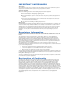
RECORDING YOUR CONNECTIONS DCT2000 AUX AUDIO IN SPDIF TO TV/VCR TO RF IN RF IN Optical R L AUDIO OUT CABLE IN S-VIDEO SWITCHED 105-125V 60Hz 4A MAX 500W MAX IR VIDEO VCR TV INPUT INPUT CABLE/ ANTENNA IN AUDIO S-VIDEO OUTPUT VIDEO AUDIO VIDEO VIDEO R L R AUDIO LEFT CABLE/ ANTENNA IN To TV L AUDIO RIGHT DVD Stereo receiver R L CD IN AUDIO OUT VIDEO OUT SPEAKER CONNECTORS VIDEO AUX IN COAX OPTICAL R L IN DIGITAL ANALOG TAPE 1 OUT A/V receiver AUDIO R L DIGITAL INPUT
Use this diagram to record cable connections from the rear panel. Later, you can use this diagram to reconnect your system if you move the equipment or add new equipment. Disconnect the power from the DCT2000 before connecting or changing cable connections. Do not place another component or object on top of the DCT2000.
BASIC OPERATION Turning Power On and Off Press POWER on the front panel to turn the DCT2000 on or off. If using the remote control, be sure it is in cable mode by pressing CABLE and then press POWER. Changing Channels You can change channels in two ways: • Press CHANNEL ▲ or ▼ on the front panel of the DCT2000, or press CHANNEL + or - on the remote control to step through the channel selection. • Enter the number of the channel you want to tune using the numeric keys on the remote control.
AUDIO/VIDEO CONNECTIONS Before you begin to hook up your DCT2000, review the following: • For basic cable connections, use 75-ohm coaxial cables equipped with F-type connectors. You can find coaxial cables in your local electronics store. • For audio or video outputs, use cables equipped with RCA and SVideo type connectors. • If you are connecting the coaxial TO TV/VCR connector on the DCT2000 to the coaxial CABLE / ANTENNA IN connector on the TV, you must tune your TV to channel 3 or 4.
CONNECTING YOUR DCT2000 RF (75 ohm) connection S-Video connection Video connection Audio connection DCT2000 AUX AUDIO IN SPDIF TO TV/VCR TO RF IN RF IN CABLE IN Optical R L AUDIO OUT VIDEO Cable in Mono TV CABLE/ ANTENNA IN 10 S-VIDEO IR SWITCHED 105-125V 60Hz 4A MAX 500W MAX
Connecting a Mono TV 1 Connect an RF coaxial cable between the cable wall outlet and the CABLE IN connector on the DCT2000. 2 Connect the RF coaxial cable, supplied with the DCT2000, between the RF IN and TO RF IN connectors on the DCT2000. 3 Connect an RF coaxial cable between the CABLE / ANTENNA IN connector on the TV and the TO TV / VCR connector on the DCT2000.
CONNECTING YOUR DCT2000 RF (75 ohm) connection S-Video connection Video connection Audio connection DCT2000 AUX AUDIO IN SPDIF TO TV/VCR TO RF IN RF IN Optical R L AUDIO OUT CABLE IN VIDEO S-VIDEO IR SWITCHED 105-125V 60Hz 4A MAX 500W MAX Cable in Stereo TV Either / or INPUT S-VIDEO VIDEO CABLE/ ANTENNA IN AUDIO LEFT AUDIO RIGHT 12
Connecting a Stereo TV 1 Connect an RF coaxial cable between the cable wall outlet and the CABLE IN connector on the DCT2000. 2 Connect the RF coaxial cable, supplied with the DCT2000, between the RF IN and TO RF IN connectors on the DCT2000. 3 Connect a RF coaxial cable between the TO TV / VCR connector on the DCT2000 and the CABLE / ANTENNA IN connector on the TV.
CONNECTING YOUR DCT2000 RF (75 ohm) connection S-Video connection Video connection Audio connection DCT2000 AUX AUDIO IN SPDIF TO TV/VCR TO RF IN RF IN Optical R L AUDIO OUT CABLE IN S-VIDEO VIDEO IR SWITCHED 105-125V 60Hz 4A MAX 500W MAX Cable in Mono VCR INPUT CABLE/ ANTENNA IN AUDIO Mono TV OUTPUT VIDEO AUDIO VIDEO CABLE/ ANTENNA IN To TV 14
Connecting a Mono TV and Mono VCR 1 Connect an RF coaxial cable between the cable wall outlet and the CABLE IN connector on the DCT2000. 2 Connect the RF coaxial cable, supplied with the DCT2000, between the RF IN and TO RF IN connectors on the DCT2000. 3 Connect a RF coaxial cable between the TO TV / VCR connector on the DCT2000 and the CABLE / ANTENNA IN connector on the mono VCR.
CONNECTING YOUR DCT2000 RF (75 ohm) connection S-Video connection Video connection Audio connection DCT2000 AUX AUDIO IN SPDIF TO TV/VCR TO RF IN RF IN Optical R L AUDIO OUT CABLE IN S-VIDEO VIDEO IR SWITCHED 105-125V 60Hz 4A MAX 500W MAX Cable in Stereo VCR INPUT CABLE/ ANTENNA IN AUDIO TV OUTPUT VIDEO AUDIO VIDEO CABLE/ ANTENNA IN To TV R L R L 16
Connecting a Mono TV and Stereo VCR 1 Connect an RF coaxial cable between the cable wall outlet and the CABLE IN connector on the DCT2000. 2 Connect the RF coaxial cable, supplied with the DCT2000, between the RF IN and TO RF IN connectors on the DCT2000. 3 Connect a RF coaxial cable between the TO TV / VCR connector on the DCT2000 and the CABLE / ANTENNA IN connector on the stereo VCR.
CONNECTING YOUR DCT2000 RF (75 ohm) connection S-Video connection Video connection Audio connection DCT2000 AUX AUDIO IN SPDIF TO TV/VCR TO RF IN RF IN Optical R L AUDIO OUT CABLE IN S-VIDEO VIDEO IR SWITCHED 105-125V 60Hz 4A MAX 500W MAX Either / or Cable in Mono VCR Stereo TV INPUT INPUT CABLE/ ANTENNA IN AUDIO S-VIDEO OUTPUT VIDEO AUDIO VIDEO VIDEO CABLE/ ANTENNA IN To TV AUDIO LEFT AUDIO RIGHT 18
Connecting a Stereo TV and Mono VCR 1 Connect an RF coaxial cable between the cable wall outlet and the CABLE IN connector on the DCT2000. 2 Connect the RF coaxial cable, supplied with the DCT2000, between the RF IN and TO RF IN connectors on the DCT2000. 3 Connect a RF coaxial cable between the TO TV / VCR connector on the DCT2000 and the CABLE / ANTENNA IN connector on the mono VCR.
CONNECTING YOUR DCT2000 RF (75 ohm) connection S-Video connection Video connection Audio connection DCT2000 AUX AUDIO IN SPDIF TO TV/VCR TO RF IN RF IN Optical R L AUDIO OUT CABLE IN S-VIDEO VIDEO IR SWITCHED 105-125V 60Hz 4A MAX 500W MAX Cable in Stereo VCR Stereo TV INPUT INPUT CABLE/ ANTENNA IN AUDIO S-VIDEO OUTPUT VIDEO AUDIO VIDEO VIDEO CABLE/ ANTENNA IN To TV R L R L AUDIO LEFT AUDIO RIGHT 20
Connecting a Stereo TV and Stereo VCR 1 Connect an RF coaxial cable between the cable wall outlet and the CABLE IN connector on the DCT2000. 2 Connect the RF coaxial cable, supplied with the DCT2000, between the RF IN and TO RF IN connectors on the DCT2000. 3 Connect a stereo audio cable between the AUDIO OUT R and L connectors on the DCT2000 and the INPUT AUDIO R and L connectors on the stereo VCR.
CONNECTING YOUR DCT2000 RF (75 ohm) connection S-Video connection Video connection Audio connection DCT2000 AUX AUDIO IN SPDIF TO T V/VCR TO RF IN RF IN Optical R L AUDIO OUT CABLE IN S-VIDEO VIDEO IR SWITCHED 105-125V 60Hz 4A MAX 500W MAX Cable in Mono VCR Stereo receiver R INPUT CABLE/ ANTENNA IN AUDIO CD IN OUTPUT VIDEO AUDIO L SPEAKER CONNECTORS VIDEO AUX IN To TV IN TAPE 1 OUT TV CABLE/ ANTENNA IN 22
Connecting a Mono TV, Mono VCR and Stereo Receiver or Amplifier 1 Connect an RF coaxial cable between the cable wall outlet and the CABLE IN connector on the DCT2000. 2 Connect the RF coaxial cable, supplied with the DCT2000, between the RF IN and TO RF IN connectors on the DCT2000. 3 Connect a RF coaxial cable between the CABLE / ANTENNA IN connector on the mono VCR and the TO TV / VCR connector on the DCT2000.
CONNECTING YOUR DCT2000 RF (75 ohm) connection S-Video connection Video connection Audio connection Optical connection DCT2000 AUX AUDIO IN SPDIF TO TV/VCR TO RF IN RF IN Optical R L AUDIO OUT CABLE IN S-VIDEO VIDEO IR SWITCHED 105-125V 60Hz 4A MAX 500W MAX Cable in Stereo VCR Stereo TV INPUT INPUT CABLE/ ANTENNA IN AUDIO S-VIDEO OUTPUT VIDEO AUDIO VIDEO VIDEO R L R AUDIO LEFT CABLE/ ANTENNA IN To TV L AUDIO RIGHT A/V receiver AUDIO R L VIDEO VIDEO S-VIDEO DIGITAL INPUT CO
Connecting Dolby® 5.1, TV, VCR and A / V Receiver 1 Connect an RF cable between the cable wall outlet and the CABLE IN connector on the DCT2000. 2 Connect the RF coaxial cable, supplied with the DCT2000, between the RF IN and TO RF IN connectors on the DCT2000. 3 Connect an optical audio cable between the OPTICAL connector on the DCT2000 and the OPTICAL connector on the A / V receiver.
CONNECTING YOUR DCT2000 RF (75 ohm) connection S-Video connection Video connection Audio connection SPDIF connection DCT2000 AUX AUDIO IN SPDIF TO TV/VCR TO RF IN RF IN Optical R L AUDIO OUT CABLE IN S-VIDEO VIDEO IR SWITCHED 105-125V 60Hz 4A MAX 500W MAX Cable in Stereo VCR Stereo TV INPUT INPUT CABLE/ ANTENNA IN AUDIO S-VIDEO OUTPUT VIDEO AUDIO VIDEO VIDEO To TV R L R AUDIO LEFT CABLE/ ANTENNA IN L AUDIO RIGHT A/V receiver AUDIO R L VIDEO VIDEO S-VIDEO DIGITAL INPUT COAX
Connecting Baseband with Dolby® Digital to a TV, VCR and A / V Receiver 1 Connect an RF cable between the cable wall outlet and the cable in connector on the DCT2000. 2 Connect the RF coaxial cable, supplied with the DCT2000, between the RF IN and TO RF IN connectors on the DCT2000. 3 Connect a stereo audio cable between the AUDIO OUT R and L connectors on the DCT2000 and the CABLE / TV AUDIO R and L connectors on the A / V receiver.
CONNECTING YOUR DCT2000 RF (75 ohm) connection S-Video connection Video connection Audio connection DCT2000 AUX AUDIO IN SPDIF TO TV/VCR TO RF IN RF IN Optical R L AUDIO OUT CABLE IN S-VIDEO SWITCHED 105-125V 60Hz 4A MAX 500W MAX IR VIDEO Cable in VCR Mono TV INPUT INPUT CABLE/ ANTENNA IN AUDIO OUTPUT VIDEO AUDIO VIDEO To TV R L R L VIDEO AUDIO CABLE/ ANTENNA IN DVD AUDIO OUT COAX OPTICAL DIGITAL 28 R VIDEO OUT L ANALOG VIDEO S-VIDEO
Connecting a Mono TV, VCR and DVD 1 Connect an RF coaxial cable between the cable wall outlet and the CABLE IN connector on the DCT2000. 2 Connect the RF coaxial cable, supplied with the DCT2000, between the RF IN and TO RF IN connectors on the DCT2000. 3 Connect a RF coaxial cable between the TO TV / VCR connector on the DCT2000 and the CABLE / ANTENNA IN connector on the VCR. 4 Connect a RF coaxial cable between the To TV connector on the VCR and the CABLE / ANTENNA IN connector on the mono TV.
CONNECTING YOUR DCT2000 RF (75 ohm) connection S-Video connection Video connection Audio connection DCT2000 AUX AUDIO IN SPDIF TO TV/VCR TO RF IN RF IN Optical R L AUDIO OUT CABLE IN S-VIDEO SWITCHED 105-125V 60Hz 4A MAX 500W MAX IR VIDEO Cable in VCR Stereo TV INPUT INPUT CABLE/ ANTENNA IN AUDIO VIDEO AUDIO VIDEO To TV R L S-VIDEO OUTPUT R L VIDEO AUDIO LEFT CABLE/ ANTENNA IN AUDIO RIGHT DVD AUDIO OUT COAX OPTICAL DIGITAL R VIDEO OUT L ANALOG Either / or 30 VIDEO S-V
Connecting a Stereo TV, VCR and DVD 1 Connect an RF coaxial cable between the cable wall outlet and the CABLE IN connector on the DCT2000. 2 Connect the RF coaxial cable, supplied with the DCT2000, between the RF IN and TO RF IN connectors on the DCT2000. 3 Connect a RF coaxial cable between the TO TV / VCR connector on the DCT2000 and the CABLE / ANTENNA IN connector on the VCR. 4 Connect a RF coaxial cable between the To TV connector on the VCR and the CABLE / ANTENNA IN connector on the stereo TV.
CONNECTING YOUR DCT2000 RF (75 ohm) connection S-Video connection Video connection Audio connection DCT2000 AUX AUDIO IN SPDIF TO TV/VCR TO RF IN RF IN Optical R L AUDIO OUT CABLE IN S-VIDEO SWITCHED 105-125V 60Hz 4A MAX 500W MAX IR VIDEO Cable in Mono VCR Stereo receiver R INPUT CABLE/ ANTENNA IN AUDIO CD IN OUTPUT VIDEO AUDIO L SPEAKER CONNECTORS VIDEO AUX IN To TV IN TAPE 1 OUT TV DVD INPUT S-VIDEO VIDEO CABLE/ ANTENNA IN AUDIO OUT COAX OPTICAL R VIDEO OUT L AUDIO LEFT
Connecting a TV, Mono VCR, DVD and Stereo Receiver or Amplifier 1 Connect an RF coaxial cable between the cable wall outlet and the CABLE IN connector on the DCT2000. 2 Connect the RF coaxial cable, supplied with the DCT2000, between the RF IN and TO RF IN connectors on the DCT2000. 3 Connect a RF coaxial cable between the CABLE / ANTENNA IN connector on the VCR and the TO TV / VCR connector on the DCT2000.
CONNECTING YOUR DCT2000 RF (75 ohm) connection S-Video connection Video connection Audio connection DCT2000 AUX AUDIO IN SPDIF TO TV/VCR TO RF IN RF IN Optical R L AUDIO OUT CABLE IN S-VIDEO SWITCHED 105-125V 60Hz 4A MAX 500W MAX IR VIDEO Cable in Stereo VCR Stereo receiver R INPUT CABLE/ ANTENNA IN AUDIO CD IN OUTPUT VIDEO AUDIO L SPEAKER CONNECTORS VIDEO AUX IN To TV IN R L R L TAPE 1 OUT TV DVD INPUT S-VIDEO VIDEO CABLE/ ANTENNA IN AUDIO OUT COAX OPTICAL R VIDEO OU
Connecting a TV, Stereo VCR, DVD and Stereo Receiver or Amplifier 1 Connect an RF coaxial cable between the cable wall outlet and the CABLE IN connector on the DCT2000. 2 Connect the RF coaxial cable, supplied with the DCT2000, between the RF IN and TO RF IN connectors on the DCT2000. 3 Connect a RF coaxial cable between the TO TV / VCR connector on the DCT2000 and the CABLE / ANTENNA IN connector on the stereo VCR.
CONNECTING YOUR DCT2000 RF (75 ohm) connection S-Video connection Video connection Audio connection DCT2000 AUX AUDIO IN SPDIF TO TV/VCR TO RF IN RF IN Optical R L AUDIO OUT CABLE IN S-VIDEO SWITCHED 105-125V 60Hz 4A MAX 500W MAX IR VIDEO TV Cable in INPUT S-VIDEO VIDEO AUDIO LEFT CABLE/ ANTENNA IN VCR AUDIO RIGHT INPUT CABLE/ ANTENNA IN AUDIO OUTPUT VIDEO AUDIO VIDEO DVD To TV R L R L AUDIO OUT COAX OPTICAL R DIGITAL VIDEO OUT VIDEO L S-VIDEO ANALOG A/V receiver AUDIO
Connecting a TV, VCR, DVD and A / V Receiver or Amplifier 1 Connect an RF coaxial cable between the cable wall outlet and the CABLE IN connector on the DCT2000. 2 Connect the RF coaxial cable, supplied with the DCT2000, between the RF IN and TO RF IN connectors on the DCT2000. 3 Connect a stereo audio cable between the AUDIO OUT R and L connectors on the DCT2000 and the CABLE / TV AUDIO R and L connectors on the A / V receiver or amplifier.
TROUBLESHOOTING Before calling your service provider, review the troubleshooting guide. This information is to help you quickly solve a problem. If your problem still exists, contact your service provider. Problem Possible Solution No sound Press MUTE on the remote control to restore the volume level. Check that the stereo is looking at the proper input source. Turn your VCR on. Check to be sure that all cables are connected properly (hand-tighten if necessary).
101 Tournament Drive, Horsham, PA 19044 800.523.6678 www.motorola.