
Installation Instructions

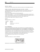
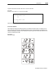


Table Of Contents
- DCT 2000 Installation Manual
- Caution | Compliance | Copyright
- Contents
- Section 1 | Introduction
- Section 2 | Overview
- Section 3 | Installation
- Before You Begin
- Installing the DCT 2000
- Standard Cabling Diagram
- STARFONE Module Cabling Diagram
- Standard VCR Cabling Diagram
- RF Bypass Switch VCR Cabling Diagrams
- A/B In Module Cabling Diagrams
- Dual A/B-RF Bypass Module Cabling Diagrams
- Composite Baseband and S-Video Cabling Diagrams
- Stereo Cabling Diagram (Baseband)
- Dolby Digital Cabling Diagrams
- Operational Check
- Section 4 | Adding the IR Blaster Option
- Section 5 | Troubleshooting
- Appendix A | Specifications
- Appendix B | Diagnostics
- Accessing Diagnostics
- Navigating the Diagnostics
- d 01: DCT 2000 General Status
- d 02: Out-of-Band Receiver Status
- d 03: In-Band Receiver Status
- d 04: In Band Error
- d 05: Unit Address
- d 06: Firmware Version
- d 07 Current-Channel Status
- d 08: Renewable Security System
- d 09: Upstream Modem Status
- d 10: Application Code Modules
- d 11: Memory Status
- d 12: Keyboard Diagnostics
- d 13: Interactive Info – OSD
- d 14: MAC Frequency – OSD
- Abbreviations and Acronyms

Diagnostics B
BB
B-
--
-11
1111
11
DCT 2000 Installation Manual
Figure B-9 shows the receiver status error count on the OSD:
Figure B-9
In-band receiver status error count short term OSD
IN-BAND RCVR STATUS
SHORT-TERM ERROR COUNT
3456
LONG TERM ERROR COUNT
7890
When there is no carrier lock, the error count displays four dashes (
−−−−
).
d 05: Unit Address
This diagnostic displays the 16-digit (40-bit) unit address of the DCT 2000. It displays in five
parts on the four-section LED. The address display stays on each section for five seconds. The
location of the dash in each of the five displays is unique. Figure B-10 shows the LEDs for unit
address 123-45678-90123-456:
Figure B-10
Unit address LEDs
MUTE
MUTE
MUTE
MUTE
MUTE
P
P
P
P
P