
Installation Instructions


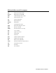

Table Of Contents
- DCT 2000 Installation Manual
- Caution | Compliance | Copyright
- Contents
- Section 1 | Introduction
- Section 2 | Overview
- Section 3 | Installation
- Before You Begin
- Installing the DCT 2000
- Standard Cabling Diagram
- STARFONE Module Cabling Diagram
- Standard VCR Cabling Diagram
- RF Bypass Switch VCR Cabling Diagrams
- A/B In Module Cabling Diagrams
- Dual A/B-RF Bypass Module Cabling Diagrams
- Composite Baseband and S-Video Cabling Diagrams
- Stereo Cabling Diagram (Baseband)
- Dolby Digital Cabling Diagrams
- Operational Check
- Section 4 | Adding the IR Blaster Option
- Section 5 | Troubleshooting
- Appendix A | Specifications
- Appendix B | Diagnostics
- Accessing Diagnostics
- Navigating the Diagnostics
- d 01: DCT 2000 General Status
- d 02: Out-of-Band Receiver Status
- d 03: In-Band Receiver Status
- d 04: In Band Error
- d 05: Unit Address
- d 06: Firmware Version
- d 07 Current-Channel Status
- d 08: Renewable Security System
- d 09: Upstream Modem Status
- d 10: Application Code Modules
- d 11: Memory Status
- d 12: Keyboard Diagnostics
- d 13: Interactive Info – OSD
- d 14: MAC Frequency – OSD
- Abbreviations and Acronyms

B
BB
B-
--
-22
2222
22 Diagnostics
DCT 2000 Installation Manual
Figure B-22 illustrates the STARFONE DIAGNOSTICS OSD:
Figure B-22
STARFONE DIAGNOSTICS OSD
STARFONE DIAGNOSTICS
MODEM TYPE : 14400 BAUD
PARAMETERS : Not Verified
BAUD RATE : 300
DATA FRMT : 8, EVEN
PHONE #1 : 6
PHONE #2 : 7
BUSY COUNT : 0
NO ANSWER COUNT : 0
LOST CARRIER COUNT : 0
CARRIER:
STAUS: HANGUP-NORMAL
Table B-20 lists the STARFONE transmitter status:
Table B-20
STARFONE transmitter status
1
st
Digit 2
nd
Digit Meaning
h*
On hook (* = hang-up code)
t–
Test for line available
d–
Dialing
A–
Waiting for answer
cr
Communicating, receiving
ct
Communicating, transmitting
c–
Communicating, idle
r*
Waiting for retry (* = hang-up code)