
Installation manual


3-4 Installation
DCT 2000 Installation Manual
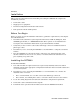
Standard VCR Cabling Diagram
Figure 3-3 illustrates the basic cabling diagram that enables you to record the channel being
viewed:
Figure 3-3
Standard VCR cabling
R
RF
IN
CABLE IN
TO RF IN
AUX AUDIO IN SPDIF
AUDIO OUT
VIDEO
SWITCHED
60Hz
500W MAX
105-125V
4A MAX
TO
TV/VCR
L
S-VIDEO
IR
VCR
DCT2000
CABLE IN VIDEO IN
AUDIO
IN
LR
CABLE OUT VIDEO OUT
AUDIO
OUT
LR
SVIDEO IN
SVIDEO OUT
TV
CABLE IN
VIDEO
IN
SVIDEO
IN
A
UDIO
IN
LR
A
UDIO
OUT
LR
From cable source
Optical
The remodulated channel, 3 or 4 does not carry stereo for digital channels. Connect the DCT2000
using RCA baseband connectors to receive stereo on digital channels. These connections are
illustrated later in this section.