
High-Defination Digital Video Recorder Installation Guide

Diagnostics 4-7
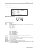
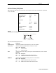
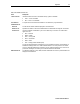
Figure 4-5
LED display for in-band diagnostic
MUTE MUTE
P
IB diagnostic
indicator
Data activity indicator
Carrier lock indicator
(L = locked, U = unlocked)
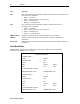
The In-Band Status fields are:
Field Description
Mode
The values displayed on the OSD are:
64 QAM — 64 QAM digital channel
256 QAM — 256 QAM digital channel
Carrier Lock
Indicates whether the in-band receiver is locked to the carrier. If a digital carrier is not
present, it indicates the carrier is not locked:
OSD LED Description
YES L Carrier locked
NO U Carrier not locked
Data
Indicates whether data is being carried on the in-band stream. The indicators cover all
packet processors, regardless of the stream they are monitoring:
OSD LED Description
YES On In-band data detected within last 5 seconds
NO Off In-band data not detected within last 5 seconds
SNR
When carrier lock has been established, displays an estimate of the carrier signal-to-noise
ratio in dB, with an explanation:
GOOD — Good value
FAIR — Marginal signal level; check the signal
POOR — Unusable signal
INVALID — Invalid SNR value
AGC
When carrier lock has been established, displays an estimate of the automatic gain
control as a percentage, with an explanation:
GOOD — Good value
FAIR — Marginal signal level; check the signal
POOR — Unusable signal
INVALID — Invalid AGC value
5 Second Error
Counts
Indicates the number of correctable and uncorrectable digital multiplex errors, up to 9999.
It is updated every 5 seconds and reset each time the DCT3412 is power cycled or
another digital multiplex is tuned. The maximum value displayed is 9999, even if there
were more than 9999 errors.
DCT3412 Installation Manual