
DVR User Manual

Diagnostics B
High-Definition DVR DCX3510-M • Installation Manual 50
365-095-17066-x.1
Diagnostics
Diagnostics are displayed on the on-screen display (OSD) and front-panel display. They
confirm proper installation, including:
• Checking error states and signal integrity
• Identifying the cable terminal on the network
• Verifying communications with the headend
For the diagnostics described in this section:
• All indicators are in decimal notation, unless otherwise noted.
• All signal-level and quality indicators use a 1% to 100% scale, unless otherwise
noted.
• All sample displays are illustrative; actual data may differ from the examples.
Using the Diagnostics
To use the diagnostics:
1. Ensure that the DCX3510-M is installed with the Thin Client software and that it is
connected to an AC outlet.
2. Ensure the set-top is powered on.
3. Press power to put the set-top in stand-by mode. Within two (2) seconds, press
select on the remote control to enable the diagnostic mode.
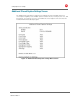
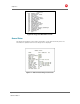
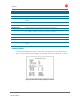
4. The Diagnostics main menu is displayed on the OSD, and d01 is displayed on the
front panel:
You can use the following keys on the remote control to navigate the diagnostics menus:
• Press channel ▲, channel ▼, cursor ▲, or cursor ▼ to select d01 through E.
• Press cursor ◄, cursor ►, select or enter to execute the selected diagnostic.
• Select E from the main menu or press power to exit.
5