
user manual


INSTRUCTION GROUPS
MOTOROLA INSTRUCTION SET INTRODUCTION 6 - 25
6.4.3 Bit Manipulation Instructions
The bit manipulation instructions test the state of any single bit in a memory location or a
register and then optionally set, clear, or invert the bit. The carry bit of the CCR will contain
the result of the bit test. The following list defines the bit manipulation instructions:
BCLR Bit Test and Clear
BSET Bit Test and Set
BCHG Bit Test and Change
BTST Bit Test on Memory and Registers
6.4.4 Loop Instructions
The hardware DO loop executes with no overhead cycles after the DO instruction itself
has been executed– i.e., it runs as fast as straight-line code. Replacing straight-line code
with DO loops can significantly reduce program memory. The loop instructions control
hardware looping by 1) initiating a program loop and establishing looping parameters or
by 2) restoring the registers by pulling the SS when terminating a loop. Initialization
includes saving registers used by a program loop (LA and LC) on the SS so that program
loops can be nested. The address of the first instruction in a program loop is also saved
to allow no-overhead looping. The loop instructions are as follows:
DO Start Hardware Loop
ENDDO Exit from Hardware Loop
Both static and dynamic loop counts are supported in the following forms:
DO #xxx,Expr ; (Static)
DO S,Expr ; (Dynamic)
Expr is an assembler expression or absolute address, and S is a directly addressable reg-
ister such as X0.
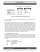
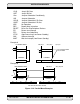
The operation of a DO loop is shown in Figure 6-13. When a program loop is initiated with
the execution of a DO instruction, the following events occur:
1. The stack is pushed.
A. The SP is incremented.
B. The current 16-bit LA and 16-bit LC registers are pushed onto the SS to
allow nested loops.
C. The LC register is initiated with the loop count value specified in the DO
instruction.