
user manual
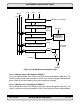

OnCE CONTROLLER AND SERIAL INTERFACE
MOTOROLA
ON-CHIP EMULATION (OnCE) 10 - 9
10.3.1.2 Exit Command (EX) Bit 5
If the EX bit is set, the processor will leave the debug mode and resume normal operation.
The Exit command is executed only if the Go command is issued, and the operation is
write to OPDBR or read/write to “No Register Selected”. Otherwise the EX bit is ignored.
10.3.1.3 Go Command (GO) Bit 6
If the GO bit is set, the chip will execute the instruction which resides in the PIL register.
To execute the instruction, the processor leaves the debug mode, and the status is reflect-
ed in the OS0-OS1 pins. The processor will return to the debug mode immediately after
executing the instruction if the EX bit is cleared. The processor goes on to normal opera-
tion if the EX bit is set. The GO command is executed only if the operation is write to
OPDBR or read/write to “No Register Selected”. Otherwise the GO bit is ignored.
10.3.1.4 Read/Write Command (R/W) Bit 7
The R/W bit specifies the direction of data transfer. The table below describes the options
defined by the R/W bit.
10.3.2 OnCE Bit Counter (OBC)
The OBC is a 5-bit counter associated with shifting in and out the data bits. The OBC is
incremented by the falling edges of the DSCK. The OBC is cleared during hardware reset
and whenever the DSP56K acknowledges that the debug mode has been entered. The
OBC supplies two signals to the OnCE Decoder: one indicating that the first 8 bits were
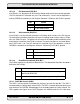
EX Action
0 Remain in debug mode
1 Leave debug mode
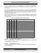
GO Action
0 Inactive (no action taken)
1 Execute instruction in PIL
R/W Action
0 Write the data associated with the command into the register
specified by RS4-RS0
1 Read the data contained in the register specified by RS4-RS0