
user manual

INSTRUCTION DESCRIPTIONS
MOTOROLA INSTRUCTION SET DETAILS A - 89
executed 65,536 times. All address register indirect addressing modes may be used to
generate the effective address of the source operand. If immediate short data is speci-
fied, the 12 LS bits of LC are loaded with the 12-bit immediate value, and the four MS
bits of LC are cleared.
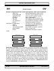
During the second instruction cycle, the current contents of the program counter (PC)
register and the status register (SR) are pushed onto the system stack. The stacking of
the LA, LC, PC, and SR registers is the mechanism which permits the nesting of DO
loops. The DO instruction’s destination operand (shown as “expr”) is then loaded into the
loop address (LA) register. This 16-bit operand is located in the instruction’s 24-bit abso-
lute address extension word as shown in the opcode section. The value in the program
counter (PC) register pushed onto the system stack is the address of the first instruction
following the DO instruction (i.e., the first actual instruction in the DO loop). This value is
read (i.e., copied but not pulled) from the top of the system stack to return to the top of
the loop for another pass through the loop.
During the third instruction cycle, the loop flag (LF) is set. This results in the PC being
repeatedly compared with LA to determine if the last instruction in the loop has been
fetched. If LA equals PC, the last instruction in the loop has been fetched and the loop
counter (LC) is tested. If LC is not equal to one, it is decremented by one and SSH is
loaded into the PC to fetch the first instruction in the loop again. If LC equals one, the
“end-of-loop” processing begins.
When executing a DO loop, the instructions are actually fetched each time through the
loop. Therefore, a DO loop can be interrupted. DO loops can also be nested. When DO
loops are nested, the end-of-loop addresses must also be nested and are not allowed to
be equal. The assembler generates an error message when DO loops are improperly
nested. Nested DO loops are illustrated in the example.
Note: The assembler calculates the end-of-loop address to be loaded into LA (the abso-
lute address extension word) by evaluating the end-of-loop expression “expr” and sub-
tracting one. This is done to accommodate the case where the last word in the DO loop
is a two-word instruction. Thus, the end-of-loop expression “expr” in the source code
must represent the address of the instruction AFTER the last instruction in the loop as
shown in the example.
During the “end-of-loop” processing, the loop flag (LF) from the lower portion (SSL) of SP
is written into the status register (SR), the contents of the loop address (LA) register are
restored from the upper portion (SSH) of (SP–1), the contents of the loop counter (LC)
are restored from the lower portion (SSL) of (SP–1) and the stack pointer (SP) is decre-
mented by two. Instruction fetches now continue at the address of the instruction follow-
DO Start Hardware Loop DO