
user manual

ADDRESSING
MOTOROLA ADDRESS GENERATION UNIT 4 - 23
3. Set Rn between the lower boundary and upper boundary in the buffer mem-
ory. The lower boundary is L x (2
k
), where L is an arbitrary whole number. This
boundary gives a 16-bit binary number “xx . . . xx00 . . . 00”, where xx . . . xx=L
and 00 . . . 00 equals k zeros. The upper boundary is L x (2
k
)+ ((2
k
)–1). This
boundary gives a 16-bit binary number “xx . . . xx11 . . . 11”, where xx . . . xx=L
and 11 . . . 11 equals k ones.
4. Use the (Rn)+ Nn addressing mode.
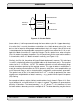
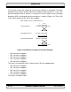
As an example, consider a 1024-point FFT with real data stored in the X memory and
imaginary data stored in the Y memory. Since 1,024=2
10
, k=10. The modifier register (Mn)
is zero to select bit-reverse addressing. Offset register (Nn) contains the value 512 (2
(k–
1)
), and the pointer register (Rn) contains 3,072 (L x (2
k
)=3 x (2
10
)), which is the lower
boundary of the memory buffer that holds the results of the FFT. The upper boundary is
4,095 (lower boundary + (2
k
)–1=3,072+ 1,023).
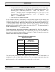
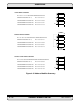
Postincrementing by + N generates the address sequence (0, 512, 256, 768, 128, 640,...),
which is added to the lower boundary. This sequence (0, 512, etc.) is the scrambled FFT
data order for sequential frequency points from 0 to 2
π. Table 4-3 shows the successive
contents of Rn when using (Rn)+ Nn updates.
The reverse-carry modifier only works when the base address of the FFT data buffer is a
multiple of 2
k
, such as 1,024, 2,048, 3,072, etc. The use of addressing modes other than
postincrement by + Nn is possible but may not provide a useful result.
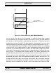
Rn Contents
Offset From
Lower Boundary
3072 0
3584 512
3328 256
3840 768
3200 128
3712 640
Table 4-3 Bit-Reverse Addressing
Sequence Example