
user manual

PROGRAMMING MODEL
5 - 8 PROGRAM CONTROL UNIT
MOTOROLA
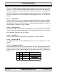
ation, move the contents in accumulator A into the location in Y data memory pointed to
by R4 and postdecrement R4. The third instruction, I3, is the same as I1, except the
rounding operation is not performed.
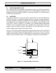
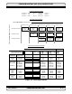
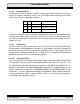
5.4 PROGRAMMING MODEL
The program control unit features LA and LC registers which support the DO loop instruc-
tion and the standard program flow-control resources, such as a PC, complete SR, and
SS. With the exception of the PC, all registers are read/write to facilitate system debug-
ging. Figure 5-4 shows the program control unit programming model with the six registers
and SS. The following paragraphs give a detailed description of each register.
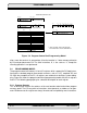
5.4.1 Program Counter
This 16-bit register contains the address of the next location to be fetched from program
memory space. The PC can point to instructions, data operands, or addresses of oper-
ands. References to this register are always inherent and are implied by most instructions.
Figure 5-4 Program Control Unit Programming Model
23 6 5 0
23 1615 0
PROGRAM CONTROL UNIT
23 1615 0
23 1615 0
*
23 1615 8 7 0
*
23 8 7 6 5 4 3 2 1 0
*
PROGRAM
COUNTER (PC)
31 SSH 16 15 SSL 0
1
15
SYSTEM STACK
STATUS
REGISTER (SR)
OPERATING MODE REGISTER (OMR)
MR CCR
MADE MB
SD
*
LOOP ADDRESS
REGISTER (LA)
LOOP COUNTER (LC)
STACK POINTER (SP)
*
*
*
* READ AS ZERO, SHOULD BE WRITTEN
WITH ZERO FOR FUTURE COMPATIBILITY
YD
MC
*