
user manual

PROGRAMMING MODEL
MOTOROLA
PROGRAM CONTROL UNIT 5 - 9
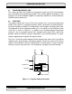
This special-purpose address register is stacked when program looping is initialized,
when a JSR is performed, or when interrupts occur (except for no-overhead fast
interrupts).
5.4.2 Status Register
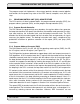
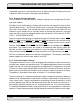
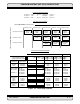
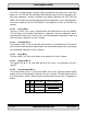
The 16-bit SR consists of a mode register (MR) in the high-order eight bits and a condition
code register (CCR) in the low-order eight bits, as shown in Figure 5-5. The SR is stacked
when program looping is initialized, when a JSR is performed, or when interrupts occur,
(except for no-overhead fast interrupts).
The MR is a special purpose control register which defines the current system state of the
processor. The MR bits are affected by processor reset, exception processing, the DO,
end current DO loop (ENDDO), return from interrupt (RTI), and SWI instructions and by
instructions that directly reference the MR register, such as OR immediate to control reg-
ister (ORI) and AND immediate to control register (ANDI). During processor reset, the
interrupt mask bits of the MR will be set. The scaling mode bits, loop flag, and trace bit will
be cleared.
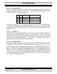
All bits are cleared after hardware reset except bits 8 and 9 which are set to ones.
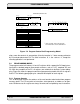
15 14 13 12 11 10 9 8 76 543210
MR CCR
*
LF DM T S1 S0 I1 I0 S L E U N Z V C
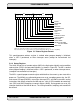
Figure 5-5 Status Register Format
CARRY
OVERFLOW
ZERO
NEGATIVE
UNNORMALIZED
EXTENSION
LIMIT
SCALING
INTERRUPT MASK
SCALING MODE
RESERVED
TRACE MODE
DOUBLE PRECISION
MULTIPLY MODE
LOOP FLAG
Bits 12 and 16 to 23 are reserved, read as zero and should be written with zero for future compatibility