
user manual

PROGRAMMING MODEL
MOTOROLA
PROGRAM CONTROL UNIT 5 - 11
5.4.2.6 Extension (Bit 5)
The extension (E) bit is cleared if all the bits of the integer portion of the 56-bit result are
all ones or all zeros; otherwise, this bit is set. The integer portion, defined by the scaling
mode and the E bit, is computed as follows:
If the E bit is cleared, then the low-order fraction portion contains all the significant bits;
the high-order integer portion is just sign extension. In this case, the accumulator exten-
sion register can be ignored. If the E bit is set, it indicates that the accumulator extension
register is in use.
5.4.2.7 Limit (Bit 6)
The limit (L) bit is set if the overflow bit is set. The L bit is also set if the data shifter/limiter
circuits perform a limiting operation; otherwise, it is not affected. The L bit is cleared only
by a processor reset or by an instruction that specifically clears it, which allows the L bit
to be used as a latching overflow bit (i.e., a “sticky” bit). L is affected by data movement
operations that read the A or B accumulator registers.
5.4.2.8 Scaling Bit (Bit 7)
The scaling bit (S) is used to detect data growth, which is required in Block Floating Point
FFT operation. Typically, the bit is tested after each pass of a radix 2 FFT and, if it is set,
the scaling mode should be activated in the next pass. The Block Floating Point FFT al-
gorithm is described in the Motorola application note APR4/D, “Implementation of Fast
Fourier Transforms on Motorola’s DSP56000/DSP56001 and DSP96002 Digital Signal
Processors.” This bit is computed according to the following logical equations when the
result of accumulator A or B is moved to XDB or YDB. It is a “sticky” bit, cleared only by
an instruction that specifically clears it.
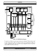
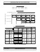
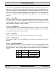
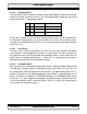
S1 S0 Scaling Mode Integer Portion
0 0 No Scaling Bits 55,54........48,47
0 1 Scale Down Bits 55,54........49,48
1 0 Scale Up Bits 55,54........47,46