TM D I G I T A L S O L U T I O N S *6881083C75* 68P81083C75-O Motorola 8000 West Sunrise Boulevard Fort Lauderdale, Florida 33322 Digital XTS 3000TM Full-Featured Model User’s Guide
Preface This manual describes how to operate an ASTRO Digital XTS 3000 Full-Featured Model Portable Radio. The full-featured model has a display, a 3 x 2 control keypad, and a 3 x 4 alphanumeric keypad. This manual first introduces you to your new radio. Then it covers general radio operation and commonly used radio features. Next, special radio features available on an ASTRO Digital XTS 3000 radio are described.
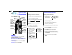
✁ Digital XTS 3000 Full-Featured Model Portable Radio COMMON RADIO FEATURE Selecting a Zone and Channel: Quick-Reference Card Concentric Switch _N/A _____ 16-Position Select Knob On/Off/ Volume Knob Top Side Button _Phone ______ Top Button _Emergency ______ A B C 0 00 S3 XT Side Button 1 _Light ______ NW ISP E D N FIR CHA DIR E PAG Softkey, Arrow, and Home Keys 3x4 Keypad ME HO F DE 3 Write your radio’s programmed features on the dotted line. Press M directly below ZONE. 3a.
Softkey Feature List COMMON and SPECIAL RADIO FEATURES Softkey Most of your radio features can be accessed by performing the following steps (for more detail, refer to the feature description in your manual). 1a. Press > until the desired softkey appears (see softkey list below). 2. 4a. If you want to change the feature state, press M directly below the desired softkey choice. OR 4b. If you do not want to change the feature state, press O or the PTT Switch.
Contents Digital XTS 3000 Portable Radio Full-Featured Model Introduction . . . . . . . . . . . . . . . . . . . . . . . . . . . . . . . . . . . . . . . . . . . . . . . . Inspection. . . . . . . . . . . . . . . . . . . . . . . . . . . . . . . . . . . . . . . . . . . . . . . . . . . Radio Controls . . . . . . . . . . . . . . . . . . . . . . . . . . . . . . . . . . . . . . . . . . . . . . . Antenna Installation and Removal . . . . . . . . . . . . . . . . . . . . . . . . . . . . . . .
Contents Special Radio Features . . . . . . . . . . . . . . . . . . . . . . . . . . . . . . . . . . . . . . . Dynamic Regrouping . . . . . . . . . . . . . . . . . . . . . . . . . . . . . . . . . . . . . . . . . PTT-ID Receive . . . . . . . . . . . . . . . . . . . . . . . . . . . . . . . . . . . . . . . . . . . . . . PTT-ID Transmit . . . . . . . . . . . . . . . . . . . . . . . . . . . . . . . . . . . . . . . . . . . . . Secure Operation . . . . . . . . . . . . . . . . . . . . . . . . . . . . . . . . . . . .
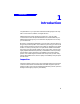
Introduction 1 Introduction Congratulations on your purchase of Motorola’s leading edge in two-way radio communications; ASTRO, the digital solution. ASTRO digital technology represents a revolution in two-way radio communication. With its expanded benefits and increased flexibility, an ASTRO digital system gives you an advanced new perspective on the way you communicate. Motorola is committed to leadership in two-way radio communications for all types of private and public use.
Introduction Radio Controls Programmable Switches and Buttons Refer to Table 1 for the features that are programmable through radio service software (RSS) to the ASTRO Digital XTS 3000 radio controls. Then write, in the space provided below the appropriate switch or button on this page, the features that apply to your radio’s programming (consult your service technician).
Introduction Table 1. Programmable Features Call Alert™ (pg. 36-43) Nuisance-Delete (pg. 47) Secure/Clear (pg. 57 ) Call Response (pg. 42) Phone (pg. 36-43) Selective Call (pg. 36-43) Channel (pg. 12-15) PL Defeat (pg. 43) Site Lock/Unlock (pg. 64) Dynamic Priority (pg. 47) Private Call (pg. 36-43) Site Search (pg. 65) Emergency (pg. 33-35) Repeater Access (pg. 43) Status (pg. 31) Keypad Mute (pg. 29) Repeater/Direct (pg. 44) Tx Power-Level (pg. 62) Light (pg. 74) Reprogram Request (pg.
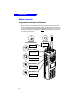
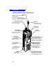
Introduction Switches, Buttons, Knobs, and Indicators Bicolor LED Indicates the radio’s operating status; Red =Transmitting Blinking Red = Channel Busy or Low Battery (while transmitting) Blinking Green = Receipt of Individual Call 16-Position Select Knob Antenna Selects the operating system (zone) and/or specific channel. Radiates and receives radio-frequency energy. Microphone Accepts audio. Speaker Emits audio. On/Off/Volume Control Knob Turns the radio on and off and adjusts the volume level.
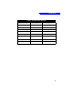
Introduction Antenna Installation and Removal Before installing the antenna, ensure that the match between your radio and antenna is correct. Your radio’s model number is on a label attached to the back of your radio. A typical model number might be H09UCC9PW5AN. The fourth position of the model number (in this example “U”) identifies the operating-frequency band of the radio. The following table lists all fourthposition alpha characters and corresponding frequency band.
Introduction Antenna Identification Table Antenna Type Approx. Length Insulator Color Code Frequency Range Antenna Kit No. in. mm VHF Wide Band Helical 8.1 203 RED 136-174MHz NAD6563 VHF Helical 7.8 7.3 6.9 195 183 172 YELLOW BLACK BLUE 136-151MHz 151-162MHz 162-174MHz NAD6566 NAD6567 NAD6568 UHF Helical 3.3 3.2 3.2 83 80 79 RED GREEN BLACK 403-435˙MHz 435-470MHz 470-512MHz NAE6546 NAE6547 NAE6548 UHF Wide Band Whip 5.
Introduction Battery Installation and Removal ! WARNING To avoid a possible explosion: DO NOT replace the battery in an area labeled “hazardous atmosphere.” DO NOT discard batteries in a fire. ! CAUTION If your radio is programmed with volatile-key retention (consult your service technician), encryption keys will be retained for approximately 30 seconds after battery removal. Note The battery is shipped uncharged, and must be charged before use.
Introduction Belt-Clip Installation and Removal Note The battery must be removed from the radio before the belt clip can be installed or removed. Installing the Belt Clip 1. 2. 3. Slide Assembly Hold the battery in one hand so that the top of the battery faces upward, and the back of the battery faces you. Holding the belt clip in the other hand with its top facing upward, align the slide assembly on the front of the belt clip with the slots on the back of the battery.
Introduction Universal Connector Cover Installation and Removal ! CAUTION When the universal connector is not in use, keep it covered with the universal connector cover. Installing the Universal Connector Cover 1. Looking at the antenna side of the radio, insert the top (flat) hooked end of the cover into the slot on the top of the radio, above the universal connector. Press downward on the cover’s top to seat it in the slot. 2.
Introduction Notes
2 General Radio Operation After a fully-charged battery and an antenna have been connected to the radio, operation may begin. If necessary, refer to page 2 to insure a complete understanding of the radio’s controls and indicators. Also, for your convenience, the “Additional Information” section (starting on page 67) contains a glossary, alert tone and status indicator tables, helpful tips, and an index.
General Radio Operation Selecting a Zone and Channel A zone is a grouping of channels. A channel is a group of radio characteristics such as transmit/receive frequency pairs. After you turn your radio on, select the desired zone and channel. • Zone Selection 1a. Press > until the ZONE softkey appears on the display. (The exact location of softkeys will vary based upon individual radio programming.) 1b. Place the Zone Switch (if programmed, see page 2) to the desired position. Then go to step 5a or 5b.
General Radio Operation 4a. Press > until the desired zone name appears on the display. 4b. Enter the number of the desired zone. FIRE DISP NW OR Note If the selected zone is unprogrammed, the display will show “UNPROGRAMMED” until a valid programmed zone is selected. This does not mean your radio is unprogrammed; only the zone you selected is unprogrammed. 5a. To select the displayed zone/ channel combination, press O. 5b. To transmit on the displayed zone/channel combination, press the PTT Switch.
General Radio Operation Method 2 Channel Selection — used when a softkey is programmed for channel selection. 1. Press > until the CHAN softkey appears on the display. FIRE DISP NW CHAN PAGE DIR 2. Press N directly below CHAN. FIRE DISP NW CHAN PAGE DIR 3. 14 The display changes to show the zone name (on steady) and the current channel name (flashing). In the example shown, “FIRE” = Zone, “DISP NW” = Channel.
General Radio Operation 4a. Press > until the desired channel name appears on the display. FIRE RESCUE1 Note 4b. Enter the number of the desired channel. OR If the selected channel is unprogrammed, the display will show “UNPROGRAMMED” until a valid programmed channel is selected. This does not mean your radio is unprogrammed; only the channel you selected is unprogrammed. 5a. When the displayed zone/ channel combination is acceptable, press O. 5b.
General Radio Operation Receiving/Transmitting After you have turned your radio on and selected the desired zone and channel, you can receive (listen to) or transmit (send) communications as follows: 1a. Listen until you hear a transmission. 1b. Press the Volume Set Button (if programmed, see page 2) to hear the volume set tone. OR A B 1c. Press the Monitor Button (if programmed, see page 2) to listen for activity. See notes below. OR C e2 pag Seeyour for o’s i rad uret fea trol ing.
General Radio Operation Using Lists The “list” feature on your radio allows you to store commonly used numbers with an identifiable name. For example, the telephone feature has an associated list of names and telephone numbers. The following general operations are available using lists: • a preprogrammed list can be viewed • a number in a list can be changed (reprogrammed) • a specific member in a list can be selected • Viewing a List 1. Press > until the VIEW softkey appears on the display.
General Radio Operation 4. 5. Press N directly below the list you wish to view. For example, to view the list of telephone numbers stored in your radio, press N directly below PHON. PHON PAGE CALL The display will show the first member in the list (name on the upper line, number on the lower line). The I status indicator will appear (on steady), indicating you are in the view mode. I FIRE CHIEF 555-8947 • FIRE RESCUE1 I On Steady = View Mode (See page 71 for a description of all status indicators.
General Radio Operation 2. Press M directly below PROG. FIRE RESCUE1 VIEW PROG PWR 3. The display changes to show the lists (PAGE, PHON, CALL, etc.) that can be changed. FIRE RESCUE1 PHON PAGE CALL 4. Press N directly below the list you wish to change. For example, to change a telephone number, press N directly below PHON. FIRE RESCUE1 PHON PAGE CALL 5. The display will show the first member in the list (name on the upper line, number on the lower line).
General Radio Operation To select a specific member from the list: 6a. Scroll through the list by pressing < or > until you locate the member’s number you wish to change. < < 6b. Go directly to a specific member in the list by entering the number (1-19) that corresponds to that member’s placement in the list. FIRST Backward OR FIRST LIST LIST LAST > LAST Forward 7.
General Radio Operation When the maximum number of digits has been entered, the cursor will disappear: 16 numbers maximum for a telephone number or 8 numbers maximum for an ID number. If you try to add any more digits, you will hear an invalid tone. Notes • In the number-edit mode, < will function as a backspace key. Pressing this key will erase the previous digit, and the cursor will move to the left.
General Radio Operation • Selecting From a List 1. Press > until the feature you desire appears as a softkey on the display. FIRE RESCUE1 For example, to select from the telephone list stored in your radio, press > until the PHON softkey appears on the display. (The exact location of softkeys will vary based upon individual radio programming.) 2. PHON PAGE CALL Press N directly below the desired feature. Using the same example in step 1, press N directly below PHON. 3.
General Radio Operation 4c. Go directly to a specific member in the list by entering the number (1–19) that corresponds to that member’s placement in the list. 4b. Scroll through the preprogrammed list by pressing < or > until you locate the desired member’s name/ number. < FIRST Backward OR FIRST LIST LIST LAST > LAST Forward Note ____ 5. If you are using the telephone feature (PHON), pressing the PTT Switch will transmit (send) the displayed number.
General Radio Operation Note • Pressing 0 twice, or M directly below the LNUM softkey, will take you to the Last telephone NUMber dialed or the Last ID NUMber transmitted/received. FIRE RESCUE1 LNUM • 24 Once the LNUM softkey is displayed, you may go directly to any member in the list by entering the number (1–19) that corresponds directly to that member’s placement within the list.
General Radio Operation General Radio Features • Radio Lock (Non-Secure Radios) The radio-lock feature enables you to select a unique numeric password. If the feature is enabled (programmable through the radio service software), you will see “RADIO LOCKED” on the display when the radio is turned on. 1. Enter your numeric password (1 to 8 characters). 2. As you enter the password digits, the radio will display dashes.
General Radio Operation • Radio Lock (Secure Radios Only) By definition, this feature changes your radio to a more robust security system, which protects the use of the secure encryption keys. If this feature is enabled (programmable through the radio service software), you will see “RADIO LOCKED” on the display when the radio is turned on. RADIO LOCKED 1. Enter your numeric password (8 characters maximum; minimum determined through radio service software). 2.
General Radio Operation 4a. If the password is correct, the radio will unlock. 4b. If the password is incorrect, the radio will remain locked. DEAD LOCKED After you enter three incorrect passwords, the radio will display “DEAD LOCKED,” and you must turn the radio off and then on in order to enter another password.
General Radio Operation 7. The display will then show “CONFIRM.” 8. Re-enter the new password and press M directly below SEL. 9a. If the two passwords match, the radio will unlock. 9b. If the two passwords don't match, the display will show “NEW PASSWORD.” You then need to repeat the previous steps. Note • You cannot change your password if you have entered three incorrect old passwords.
General Radio Operation • Muting the Keypad Tones The radio’s keypad tones, normally heard each time a keypad key is pressed, can be turned off (muted) or on (unmuted) at your discretion. Muting Keypad Tones Using the Keypad-Mute Switch: Note The Keypad-Mute Switch is programmable through radio service software. To turn the keypad tones off, put the Keypad-Mute Switch in the “tones off” position.
General Radio Operation • Time-Out Timer The new ASTRO portable radio is equipped with a programmable time-out timer which, upon expiration, will turn off the transmitter. This timer is programmable through radio service software and can be set from 0 seconds (off) to 7.75 minutes (465 seconds), at 15 second increments. The ASTRO radios have been programmed at shipment for 60 seconds. 1. A time-out timer warning occurs approximately four seconds before the allocated time-out timer expires.
3 Common Radio Features Data Calls (Status Calls or Message Calls) This feature allows you to send data calls (status calls or message calls) from your radio to the dispatcher to indicate a predefined condition. Each defined status or message can have a 12-character alias. You can have the following maximum number of predefined conditions: 16 message conditions; 16 status conditions for conventional; 8 status conditions for trunking. • Sending a Status Call or Message Call 1a.
Common Radio Features 3. The last acknowledged status call or the first message in the message list will be displayed. Note If no status has been acknowledged, the first status in the status list will be displayed. 4a. Scroll through the list by pressing < or > until you locate the predefined condition you wish to send. < FIRST Backward 4b. Go directly to a specific predefined condition in the list by entering the number that corresponds to that condition’s placement in the list.
Common Radio Features Emergency For radios programmed with the emergency feature, pressing the Emergency Button (if programmed, see page 2) will send out an emergency signal that takes precedence over any other signalling activity in progress on the selected channel. There are two types of emergency signals: • • Emergency Alarm sends a data transmission to alert the dispatcher to an emergency condition and identify the radio sending the emergency signal.
Common Radio Features 3a. Emergency Alarm During a non-silent emergency alarm state: • • • • 3b. Silent-Emergency Alarm 3c. Emergency Call Press the PTT Switch. During a silentemergency state: OR the LED will light, a short, mediumpitched tone will be heard, the display will show “EMERGENCY,” when the emergency alarm is acknowledged by the dispatcher, the radio sounds four beeps and the alarm ends.
Common Radio Features • Exiting the Emergency State It is important that you exit the emergency state when you have finished. There are four ways to exit the emergency state: 1. Press the Emergency Button for approximately 1 second (this time is programmable through radio service software); a medium-pitched, emergency-exit tone sounds until the button is released and the radio returns to normal operation. 2.
Common Radio Features Individual Calls Individual calls are defined as follows: • Telephone Calls — similar to standard telephone calls, except you use your radio. These calls can be landline caller to radio, radio to landline caller, or landline caller to radio talkgroup. • Private-Conversation™ II Calls (Private Calls) — one-on-one calls involving two specific radios in which the conversation will not be heard by others in the current radio talkgroup.
Common Radio Features • Selecting the Feature Note On conventional channels, you must monitor the channel for activity before making an individual call (see page 16 for details). 1a. Press > until one of the following 1b.
Common Radio Features • Using the Feature 1. Telephone Calls Only — Your radio may be programmed to automatically access the telephone system (immediate access/auto access) or wait for you to do something (manual access/delayed access); consult your service technician to determine which way your radio was programmed. • Immediate Access: The display will show “PLEASE WAIT” while your radio attempts to access the telephone system.
Common Radio Features If the display shows “NO PHONE” or you do not hear a dial tone in any of the above situations, “hang up” (disconnect) by pressing O or the designated quick-access button (Phone, Private Call, Selective Call, or Call Alert Button). If the display shows “PHONE BUSY,” your call is placed in queue until a line is available. When a line becomes available, the display changes to “PLEASE WAIT” and a dial tone is heard. 2. If the party you are calling answers, converse in the normal manner.
Common Radio Features • Calling the Last Number Dialed or Last ID Number Transmitted/Received For Telephone Calls Only — Press the PTT Switch. You will either hear ringing or a busy tone. On a trunking system, if you hear a busy tone, press the PTT Switch to try again. Otherwise, press O to exit the Telephone Call feature. A B C 0 00 S3 XT For Private-Conversation Calls Only — Press the PTT Switch. Begin talking. For Enhanced Private-Conversation Calls Only — Press the PTT Switch.
Common Radio Features • Calling a New Number (if enabled through radio service software) Enter a new phone number or ID number using any of the numeric (0–9) keys; then press the PTT Switch (see following note). This action does not “program” a new number in your radio’s memory list; this is a temporary number only. The first digit of the new number will be shown, and a blinking cursor, indicating the position of the next number to be added, is also displayed.
Common Radio Features • Answering an Individual Call 1. When an individual call is being received, you will hear and/or see: • a telephone-type ringing if it is a telephone call; • two alert tones if it is a Private-Conversation call or selective call; • a continuous cycle of four tones if it is a Call-Alert page; • the LED blinking green; • the F indicator flashing; and • the display will show one of the following: F PHONE CALL Telephone Call 2a.
Common Radio Features 3. Converse in the normal manner. Press the PTT Switch to talk; release the PTT Switch to listen. Talk = 4. Press & Hold PTT Switch Listen = Release PTT Switch A B C 0 00 S3 XT When you have finished your conversation, “hang up” (disconnect) by pressing O. The radio will return to the home display. PL Defeat The PL defeat feature allows you to override any coded squelch (DPL, PL, or network ID) that may be programmed to a channel.
Common Radio Features Repeater/Direct The repeater/direct feature allows you to bypass the repeater and talk directly to another radio. This is known as DIRECT operation or talkaround operation. The transmit frequency is the same as the receive frequency. In REPEATER operation, you talk through the repeater, which increases the radio’s operating range. The transmit frequency is not the same as the receive frequency. • Selecting Repeater or Direct Operation 1a. Press > until DIR appears on the display.
Common Radio Features Scan H FIRE DISP NW G = Scan Feature Active CALL PHON SCAN The scan feature allows you to monitor activity on different channels by scanning a “scan list.” Each radio can have up to 20 different scan lists. The channels to be scanned can be programmed with the radio service software or manually by using the keypad.
Common Radio Features • Turning Scan On and Off 1a. Press > until SCAN appears on the 1b. Place the Scan On/Off Switch display. (if programmed, see page 2) in the “scan on” position or the “scan off” position. OR FIRE DISP NW CALL PHON SCAN A 2. B C e2 pag Seeyour for o’s i rad uret l a e g. f tro min congram pro Press M directly below SCAN. FIRE DISP NW CALL PHON SCAN 3. The display will show the current scan state. SCAN ON ON 4.
Common Radio Features • Deleting Nuisance Channels When the radio scans to a channel that you do not wish to hear (nuisance channel), you can temporarily delete the channel from the scan list. 1. When the radio is locked onto the channel to be deleted, press the Nuisance-Delete Button (if programmed, see page 2). Repeat this step to delete additional nuisance channels. Notes Priority channels and the selected channel cannot be deleted using the nuisance-delete feature.
Common Radio Features • Programming a Scan List Notes 1. Priority channels and the selected channel cannot be deleted using the nuisance-delete feature. Press > until the PROG softkey appears on the display. FIRE RESCUE1 VIEW PROG SCAN 2. Press M directly below PROG. FIRE RESCUE1 VIEW PROG SCAN 3. The display changes to show the lists (PHON, CALL, SCAN, etc.) that can be changed; use < or > to see other available lists. FIRE RESCUE1 CALL PHON SCAN 4. Press M directly below SCAN.
Common Radio Features 5. The display will show the first member in the list. The I status indicator will appear (flashing), indicating you are in the programming mode. I FIRE DISP NW I Flashing = Programming Mode SEL DEL 6a. Press M below the desired state (SEL or DEL). SEL = add currently displayed OR channel to the scan list DEL = delete currently displayed channel from the scan list Notes 6b.
Common Radio Features 7a. Use < or > to select additional channels to be added or deleted from the scan list. 7b. Use the keypad to 7c. go directly to a channel number to be added or OR OR deleted from the scan list. Rotate the 16Position Select Knob to select additional channels to be added or deleted from the scan list. A B C 0 00 S3 XT 8. Press O to exit the scan list programming mode. Notes 50 The following notes are dependent upon your radio’s programming; consult you service technician.
Common Radio Features Selecting Squelch Operation Tone Private-Line® (PL), Digital Private-Line™ (DPL), network ID, and carrier squelch operations are all available in the same radio on a per channel basis. Note Network ID is only available on ASTRO “digital” channels (consult your service technician). When in carrier squelch operation, all traffic on the channel is heard. When in PL, DPL, or network ID operation, your radio responds to only those messages intended for you.
Common Radio Features Smart PTT Smart PTT is a per-channel, programmable feature used in conventional radio systems to keep radio users from talking over other radio conversations. When smart PTT is enabled in your radio, you will not be able to transmit on an active channel. If you try to transmit (press the PTT Switch) on an active smart-PTT channel, an alert tone will be generated, and the transmission will be inhibited. The LED will also blink red to indicate that the channel is busy.
Special Radio Features 4 Special Radio Features Dynamic Regrouping The dynamic regrouping feature allows the dispatcher to temporarily reassign selected radios to a single special channel so that they can communicate with each other. This feature, enabled in each radio by means of the radio service software, is typically used during special operations. You will not notice whether your radio has this feature enabled until a dynamic regrouping command is sent by the dispatcher. Note 1.
Special Radio Features 2. Talk and listen as usual. 3a. For Radios Using Only Softkeys for Zone and Channel Selection — 3b.
Special Radio Features • Select Enable/Disable The dispatcher may classify regrouped radios into either of two categories: select enabled or select disabled. • Select-enabled radios are free to make channel changes to any available channel, including the dynamic-regrouping channel. • Select-disabled radios cannot change channels since the dispatcher has specifically chosen to force the radio to remain on the dynamicregrouping channel.
Special Radio Features PTT-ID Receive The PTT-ID receive feature allows you to see the radio ID number of the radio you are currently receiving. This ID can be a maximum of eight characters and can be viewed by both the receiving radio and the dispatcher. On trunking radios, pressing < or > will replace the displayed ID with the softkey menu selections; pressing O will bring back the ID display.
Special Radio Features Secure Operation Note • Secure operation provides the highest level of commercially available voice security on trunked or conventional channels. Unlike other forms of security, Motorola digital encryption provides signalling that makes it virtually impossible for others to decode any part of an encrypted message.
Special Radio Features • Managing Encryption KEY Loading 1. Refer to the key-variable loader (KVL) manual for equipment connections and setup. 2. When the KVL is attached to your radio, the display will show “KEYLOADING,” and all other radio functions will be locked out. 3. KEYLOADING Pressing the KVL’s PTT Switch will load the encryption keys into your radio.
Special Radio Features KEY Erasure (All KEYS Erased) — Method 2 1. With the radio on, press and hold the Top Side Button; while holding this button down, press the Emergency Button. Note 2. DO NOT press the Emergency Button before pressing the Top Side Button unless you are in an emergency situation; this would send an emergency alarm. When all the encryption keys are erased, the display will show “ERASED.
Special Radio Features 4a. Press < or > to scroll through OR the encryption keys. Note 5. 4b. Enter the number of the desired index. If an erased key is selected, the key name will be alternated with “ERASED KEY.” Press M directly below the desired softkey, or if you did step 4b, press < or > to scroll through the menu selections. PSET or “PRESET” = selects the preset or default encryption key. SEL = saves the newly-selected key and returns to the home display. 6.
Special Radio Features 4a. Press M directly below the desired index. 5. OR 4b. Enter the number of the desired index. To save the newly selected index, press N below SEL. The radio will then exit index selection and return to the home display. Note Pressing O or the PTT Switch or turning the 16-Position Select Knob will exit this display menu without changing the index selection.
Special Radio Features Selectable Power-Level This feature allows you to select the power level at which your radio will transmit messages. Note The radio will always turn on to the default setting as determined through radio service software. 1a. Press > until the PWR softkey appears on the display. OR Press M directly below PWR. 2. 1b. Press the TX Power-Level Switch (if programmed, see page 2). This will take you directly to step 3. A B C e2 pag Seeyour for o’s i rad uret fea trol ing.
Special Radio Features Trunking System Controls • Busy Override When a talkgroup call is placed in a SmartZone™ system and the system is not able to obtain voice channels at all necessary sites, a busy tone will be generated. If so programmed in the zone manager and through the radio service software, you may override this busy by performing the following steps: 1. Press the PTT Switch; a busy indication is received. 2. Release the PTT Switch. 3. Press and hold the PTT Switch a second time.
Special Radio Features • Failsoft If a trunking system experiences a complete failure, the radio will revert to failsoft operation and automatically switch to its failsoft channel. During failsoft, the trunking repeaters will transmit a medium-pitched tone every 10 seconds. When the trunking system returns to normal operation, your radio will automatically leave the failsoft operation and return to trunked operation.
Special Radio Features • Site Trunking If the zone dispatcher loses communication with any site, that site will revert to what is known as “site trunking.” Your radio will alternately display “SITE TRUNKNG” and the currently selected zone/channel combination. When this occurs, you will only be able to communicate with other radios within your trunking site. SITE TRUNKNG • Site View and Change Viewing the Current Site 1. Momentarily press the Site Search Button (if programmed, see page 2). 2.
Special Radio Features Notes 66
5 Additional Information Glossary ACK Acknowledgement of communication Channel A group of characteristics such as transmit/receive frequency pairs, radio parameters, and encryption encoding Control Channel In a trunking system, one of the channels that is used to provide a continuous, two-way/data communications path between the central controller and all radios on the system Conventional Typically refers to radio-to-radio communications, sometimes through a repeater; does not use a trunking (contro
Additional Information PTT Push-To-Talk - the PTT switch engages the transmitter and puts the radio in transmit (send) operation when pressed Radio-To-Landline Communicating from a portable/mobile radio through the telephone system.
Additional Information Alert Tones Sound Tone Name Occurs: Invalid Key-Press when the wrong key is pressed Radio Self-Test Fail Short, Low-Pitched Tone when the radio fails to receive an No ACK Received acknowledgement from the dispatcher Reject Continuous, Low-Pitched Tone A Group of LowPitched Tones (Busy Tone) Short, Medium-Pitched Tone when the radio fails its power-up self test when an unauthorized request is made Time-Out Timer Warning four seconds before time out Time-Out Timer Timed Out
Additional Information Sound Continuous, Medium-Pitched Tone Tone Name Volume Set when volume changed on a quiet channel Emergency Exit upon exiting the emergency state PTT Sidetone Failsoft Automatic Call Back A Group of Medium-Pitched Tones Occurs: when data is sent by pressing the PTT switch, but the user must wait to talk when system fails when voice channel is available from previous request Talk Permit upon pressing the PTT switch; verifying system accepting transmissions DispatcherInterrup
Additional Information Status Indicators Symbol Indicator Name B Battery Status C Carrier Squelch indicates the radio is operating in the carrier-squelch mode D Secure Operation appears when your radio is in secure operation; on (D) = secure; off (E)= clear-operation F Call Received flashes when an individual call is received G Scan H (Dot Flashing) Priority-One Channel Scan indicates when the radio is in priority-one channel scan operation H (Dot Steady) Priority-Two Channel Scan indi
Additional Information Battery Charging and Disposal • Charging Batteries This product is powered by a nickel-cadmium (Ni-Cd) or nickel-metal-hydride (NiMH) rechargeable battery. Charge the battery before use to ensure optimum capacity and performance. The battery was designed specifically to be used with a Motorola charger. Charging in non-Motorola equipment may lead to battery damage and void the battery warranty.
Additional Information For disposal, NiCd batteries should be delivered to an authorized metals reclamation dealer. NiMH batteries, although they contain no designated toxic metals, are recommended to be disposed of through an authorized metalsreclamation dealer. In addition, U.S. Environmental Protection Agency (EPA) regulations classify used Ni-Cd batteries as hazardous waste, unless certain exemptions apply. Motorola fully endorses and encourages the recycling of Ni-Cd batteries.
Additional Information Helpful Tips • If poor light conditions make the display, keypad, or channel numbers (around the 16-Position Select Knob) difficult to read, turn on the radio’s display, keypad, and channel backlights by pressing the Light Button (see page 2). These lights will remain on for a preprogrammed time before they turn off automatically, or you can turn them off immediately by pressing the Light Button again.
Additional Information Radio Care • Cleaning Clean external surfaces of your radio with the following solution: one teaspoon of mild dishwashing detergent to one gallon of water (0.5% solution). ! CAUTION Do not use solvents to clean your radio; spirits may be harmful and permanently damage the radio housing.
Additional Information Air Bag Safety Information ! WARNING An air bag inflates with great force. DO NOT place objects, including communications equipment, in the area over the air bag or in the air bag deployment area If the communication equipment is improperly installed and the air bag inflates, this could cause serious injury. • Installation of vehicle communication equipment should be performed by a professional installer/technician qualified in the requirements for such installations.
Index Index A ABRT softkey . . . . . . . . . . . . . . . . . . . . . . . . . . . . . . . . . . . . . . . . . . . . . . . . . .58 Alert Tones . . . . . . . . . . . . . . . . . . . . . . . . . . . . . . . . . . . . . . . . . . . . . . . . . . .69 ALL softkey . . . . . . . . . . . . . . . . . . . . . . . . . . . . . . . . . . . . . . . . . . . . . . . . . . .58 Antenna . . . . . . . . . . . . . . . . . . . . . . . . . . . . . . . . . . . . . . . . . . . . . . . . . . . .4, 5 Arrow Keys . . . . . . . . . . .
Index H HIGH softkey . . . . . . . . . . . . . . . . . . . . . . . . . . . . . . . . . . . . . . . . . . . . . . . . . .62 Home Key . . . . . . . . . . . . . . . . . . . . . . . . . . . . . . . . . . . . . . . . . . . . . . . . . . . . .4 I ID. . . . . . . . . . . . . . . . . . . . . . . . . . . . . . . . . . . . . . . . . . . . 37, 40-42, 51, 56, 70 Inmediate Access. . . . . . . . . . . . . . . . . . . . . . . . . . . . . . . . . . . . . . . . . . . . . . .38 Index . . . . . . . . . . . . . . . . . . . .
Index P “P” . . . . . . . . . . . . . . . . . . . . . . . . . . . . . . . . . . . . . . . . . . . . . . . . . . . . . . . . . .21 PAGE softkey . . . . . . . . . . . . . . . . . . . . . . . . . . . . . . . . . . . . . . . . .17, 18, 37, 56 Password . . . . . . . . . . . . . . . . . . . . . . . . . . . . . . . . . . . . . . . . . . . . . . . . . . 25-27 PHON softkey . . . . . . . . . . . . . . . . . . . . . . . . . . . . . . . . . . .17, 18, 22, 23, 37, 48 PL . . . . . . . . . . . . . . . . . . . . . . . .
Index T Talkaround . . . . . . . . . . . . . . . . . . . . . . . . . . . . . . . . . . . . . . . . . . . . . . . .44, 71 Telephone Call . . . . . . . . . . . . . . . . . . . . . . . . . . . . . . . . . . . . . . . . . . . . . 36-42 Time-Out Timer . . . . . . . . . . . . . . . . . . . . . . . . . . . . . . . . . . . . . . . . . . . .30, 69 Transmit . . . . . . . . . . . . . . . . . . . . . . . . . . . . . . . . . . . . . . . . . . . . . . . . . . . . .16 TX Power-Level . . . . . . . . . . . . . . . . . . .
Notes
Notes
QUESTIONNAIRE We believe that reports from users provide valuable information for producing quality operating instructions. Your comments and answers to the following questions will aid us in preparing manuals that contain accurate and complete information of maximum benefit to you. In reference to Manual No.
NO POSTAGE NECESSARY IF MAILED IN THE UNITED STATES BUSINESS REPLY MAIL FIRST CLASS MAIL PERMIT NO 9040 FT. LAUDERDALE, FL POSTAGE WILL BE PAID BY ADDRESSEE Attention: Technical Communications 8000 W. Sunrise Boulevard Ft.