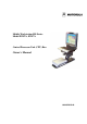
Mobile Workstation 800 Series Model F5207A, F5217A Central Processor Unit (CPU) Box Owner’s Manual 6802976C60-O
MW800 CPU Owner’s Manual COMPUTER SOFTWARE COPYRIGHTS The Motorola products described in this instruction manual may include copyrighted Motorola computer programs stored in semiconductor memories or other media. Laws in the United States and other countries preserve for Motorola certain exclusive rights for copyrighted computer programs, including the exclusive right to copy or reproduce in any form the copyrighted computer program.
TABLE OF CONTENTS Using this Manual .......................................................................................................................................... 5 Who Should Use this Manual .................................................................................................................... 5 Manual Introduction .................................................................................................................................. 5 Related Manuals ..................
MW800 CPU Owner’s Manual Features.....................................................................................................................................................43 Appendix F: Auxiliary Port Layout ..................................................................................................46 Appendix G: Approved Accessories/Options ....................................................................................48 Appendix H: CPU Factory Default Setting ....................
Using this Manual Before using this manual and products it describes, be sure to read the Safety instructions in Appendix A, the Warranty information in Appendix B and the FCC information in Appendix C. Who Should Use this Manual This manual is intended for staff who operate the Mobile Workstation 800 (MW800) and need to configure, upgrade or maintain its CPU box. This manual assumes the reader is familiar with the MW800 and basic Windows operations.
MW800 CPU Owner’s Manual • • • • • • Appendix H: Appendix I: Appendix J: Appendix K: Appendix L: Appendix M: CPU factory setup Differences between F5207A and F5217A models BIOS factory setup Dual display configuration Troubleshooting information Acronyms and Abbreviations Related Manuals This manual describes the MW800 CPU box and provides basic operating instructions.
Note: Indicates an operational procedure, practice, or condition to which you should pay special attention. CAUTION: Alerts you of conditions, which can result in loss or corruption of data, or damage to device. DANGER: Indicates a potentially hazardous situation, which, if not avoided, may result in injury. It may also be used to alert against unsafe practices and property-damageonly accident hazards.
MW800 CPU Owner’s Manual Section 1: Getting Started What is the CPU Box? The Motorola Mobile Workstation 800 (further MW800) series is Motorola's highest-performing and most rugged data communication and computing solution. It is specifically designed for the harsh conditions of the mobile environment--areas not suitable for conventional notebook or desktop computers. Refer to Appendix D for detailed specifications.
Section 2: Basic Operations This section describes the following operations: • • • • • Power On Power Off Standby Wake Up Reset Power On This chapter describes methods to power on the CPU box in normal and extreme conditions. NOTE: Prior to powering on the CPU, ensure that the main power switch on the rear CPU panel is in the ON position. Normal operation The CPU box can be turned on either from the vehicle ignition switch or by the power button located on the front panel.
MW800 CPU Owner’s Manual Low Temperature Conditions The device supports working hard disk conditions even if it’s turned off. When the ambient temperature drops below the low hard disk operational limit, an internal heater will automatically adjust and maintain the working conditions (see Hard disk heating when device is off parameter in section 3) for pre-defined time.
Normal Operation The CPU box can be turned off either by the vehicle ignition switch or by the power button located on the front panel. The CPU box can also be turned off with the Windows Shut Down process. Remember to save important information before turning the device off. • If the CPU box is connected via the ignition and configured to be powered off by the ignition switch (see section 3, Ignition shut down preference setting is SHUTDOWN), rotate the car key it to OFF position.
MW800 CPU Owner’s Manual • Internal temperature exceeds the high operational limit. If during operation the ambient temperature exceeds the operating temperature range or internal temperature exceeds the high operational limit for any reason, the CPU processor gradually slows down, and eventually powers off. A message ”CPU temperature is high. The system will shutdown in 3 minutes. Please save your work” will warn you about this event.
Resume If the device is in Standby mode, the following methods will resume it: • • • • • • • • • Ring Indicator from a serial port USB bus activity An input from the keyboard Changing a touch pad position A contact to the touch panel of the MW800 display Pressing the Emergency key of the MW800 display Pressing the Function key of the MW800 display LAN (Wake on LAN message) Power button (if configured) If the CPU box configuration allows wake up from a serial port (see section 3, Radio ring indicator (
MW800 CPU Owner’s Manual CAUTION: If the system does not respond, you can turn the device off by pressing and holding the power button for 6 seconds or more. Be aware, this method of hardware power off may damage your hard disk.
Section 3: CPU Configuration The CPU has a protected memory area to store the configuration parameters accessed when you turn it on. That binary-format data contains basic information about CPU capabilities including general settings, power-up, power-off modes, etc. This chapter describes the various configuration parameters that can be selected and modified as required. CPU Configuration Parameters Power source Provides capability to select a power source: either 13.8VDC or 9VDC car batteries.
MW800 CPU Owner’s Manual Ignition shut down preference Selects desired CPU action when turning the ignition switch off. The following options are available: • • NONE SHUTDOWN Ignore turning the ignition switch off. Shut the device down when the ignition switch is turned off. If this option is selected, set Ignition shutdown timeout, which specifies the period to elapse between turning off the ignition switch and the CPU shutting down. Factory setting is NONE.
Selects initial mode of a GPS receiver if your CPU is fitted with the internal Trimble GPS unit. Factory setting is OFF. GPS mode This parameter is pertinent if your CPU is fitted with the internal Trimble GPS device. It selects the standard protocol used by GPS receiver to transmit data. The NMEA and TSIP/TAIP options are available. Factory setting is TSIP/TAIP for F5207A and NMEA for F5217A. Radio ring indicator (RI) Enables or disables wake-up from the RI line of the serial COM3 port.
MW800 CPU Owner’s Manual BIOS Setup The BIOS is a program stored on a Flash chip on the motherboard with a default configuration that starts when you turn on the CPU. The device provides a BIOS Setup Utility that enables the selection and modification of different BIOS setup parameters. Note that incorrect BIOS changes can prevent the device from working. Factory BIOS setting can be found in Appendix J.
Figure 2. Codeplug Editor To modify configuration parameters use the MPS tool as the following: • • • • • Click on Read from CPU to read the codeplug parameters. If your device is successfully read, you will see CPU parameters. Click on Save to file to backup the original codeplug data. Modify a parameter per your selection. Click on Write to CPU to program the device. If the device is successfully programmed, the following message appears.
MW800 CPU Owner’s Manual Section 4: CPU Software This manual assumes that you are familiar with basic Windows operations. If this is not the case, be sure to read the documentation that came with your version of Windows before you proceed. This chapter contains the information about unique CPU software and firmware components. For documentation of supplied software applications, refer to the help file attached to each application.
Figure 4. CPU Manager, Lines Control Tab • Power The CPU current consumption and a voltage level of the car battery Figure 5.
MW800 CPU Owner’s Manual Figure 6. CPU Manager, Temperature Tab • Agent Notifications ◊ ◊ ◊ ◊ Temperature Alerts if a corresponding event occurs. The following notifications are available: - when CPU temperature exceeds either limit of the valid range. Low battery - when the battery voltage drops below 10.5VDC. Ignition - when you turn off the ignition switch. Current Notifications - when CPU box experiences over-current of hard drive heater, firewire device or PC card.
Figure 7. CPU Manager, Notifications Tab • Logger Troubleshooting tool allowing documentation of extreme events into a log file Figure 8.
MW800 CPU Owner’s Manual MW800 Display Utilities This application provides the following capabilities: • Calibration Tool • ExtraKey Application • • MW Display Tester Volume Bar calibrates the touch screen interface to the display monitor configures the MW800 display functional buttons for other Windows applications troubleshoots several display problems sets of the current volume level Calibration Sometimes there is a need to calibrate the touch panel attached to the display monitor, i.e.
• Double-Click Setting calibrates the double-click on the touch screen ExtraKey Application The ExtraKey Application allows display function keys to be configured for other Windows applications. It allows the function key to operate like the standard keyboard hotkey, launch any application (like Notepad or Calculator) or blank the display. ExtraKey application's desktop toolbar is situated on one of the edges of the screen (default - the bottom edge).
MW800 CPU Owner’s Manual How to set a shortcut to the display switch • • Choose Display switch in the Map to drop-list. Field Name defines how the Extrakey Bar button will be named (this is optional). The ExtraKey Application on-line help provides context-sensitive information. Please, read this information to ensure proper operation of the device. Display Tester This tool is simple test application for troubleshooting certain display features. This tool is for display diagnostics purposes, only.
Section 5: Software/Firmware Upgrade Software upgrades keep your computer up-to-date. All software components, utilities and applications described in this chapter are PC-based, running under Windows 2000 and Windows XP operating systems on the MW800 series or compatible platform. The MW800 Support CD-ROM part No. FVN5413A is an auto-run software package. Use this kit when you installing or updating unique software and firmware components in your device.
MW800 CPU Owner’s Manual • Chipset Installation • Extreme Graphics • Embedded Graphics • • LAN WLAN • • • Sound driver Video Capture Windows SP Updates the Windows *.INF files in your device. The INF files inform the operating system how to properly configure the chipset for specific functionality, such as USB and core PCI. Updates or install the Extreme Graphics video driver.
• Write new BIOS to the mainboard. CAUTION: Writing new BIOS to the flash chip is a very sensitive procedure, improper BIOS upgrade could make the device inoperable. Note: Always back up your current BIOS. If something goes wrong, the previous one can always be restored. If upgrading of the BIOS is required, carry out the following steps: • • • • • • • • Close all other programs. Go to Program menu and click WinPhlash to execute the program. Main window will appear on the screen.
MW800 CPU Owner’s Manual Figure 12. EC Loader Setup • Click on Start Programming button to begin programming. EC Programming dialog appears; the progress bar will show programming status. Figure 13. EC Loader Programming • Wait for completion of programming process. When completed EC Flash Programming has passed successfully will appear.
Figure 14. Successful Programming Applications Insert the Support Kit into the CD-ROM drive and click on the Applications button.
MW800 CPU Owner’s Manual application programming interfaces (API’s) built into Microsoft Windows operating systems. NOTE: Microsoft WM Capture Tool, Windows Media Player 9 and Microsoft DirectX 9.0c are available only for Windows 2000. Manual CPU Manager Update You can manually update the CPU Manager in your device as follows: • • Remove the current version of CPU Manager. Go to Control Panel -> Add and Remove Programs, select MW800 CPU Manager and click Change/Remove button.
Section 6: Recovery of pre-installed software This section provides a view of general maintenance and recovery techniques. Motorola provides a recovery CD with your computer that allows reinstallation of the complete Windows operating system, device drivers, applications, and parameters similar to the default factory settings. CAUTION: Personal settings, additional applications and data will be lost during recovery procedure.
MW800 CPU Owner’s Manual To reinstall a program, from the Add/Remove Programs Properties window, click Install, and then follow the instructions on the screen. Recovering the hard disk to factory contents from recovery CD (only for Windows 2000) If your hard disk data is completely damaged and none of above procedures helps, you can recover the hard disk software image similar to the initial factory install with the recovery CD. To recover the hard disk, do the following: • Turn the CPU off.
Section 7: Getting Assistance from Motorola For your convenience, the Motorola Web site provides up-to-date information about the MW800. The address for MW800 home page is http:/www.motorola.com. This site includes general information about the device, as well as answers to questions regarding operational issues with the MW800.
MW800 CPU Owner’s Manual Appendix A: Safety Instructions DANGER: Reduce the risk of fire or electric shock by following basic safety instructions: • Do not use your device during electrical storms. • Do not connect or disconnect cables while you device is turned on. • Protect your device from liquids. Keep your device away from water. • Do not use any power cord where input or output pins show signs of corrosion or overheating.
If you opened the device to add or upgrade a memory card or Mini PCI card or any other component, do not use your device until you have re-assembled the entire unit. Never use the device when cover(s) is open. CAUTION: The CMOS battery can degrade when your device is not used for a long period of time. Leaving a battery in a discharged state could shorten a lifetime of the battery. CAUTION: The device automatically shuts down when the internal temperature exceeds the upper limit of the valid range.
MW800 CPU Owner’s Manual Appendix B: Warranty Information EPS – 34440- B This warranty applies within the fifty (50) United States, the District of Columbia and Canada. LIMITED WARRANTY MOTOROLA COMMUNICATION PRODUCTS If the affected product is being purchased pursuant to a written Communications System Agreement signed by Motorola, the warranty contained in that written agreement will apply. Otherwise, the following warranty applies. I. WHAT THIS WARRANTY COVERS AND FOR HOW LONG: Motorola Inc.
DAMAGES IN EXCESS OF THE PURCHASE PRICE OF THE PRODUCT, FOR ANY LOSS OF USE, LOSS OF TIME, INCONVENIENCE, COMMERCIAL LOSS, LOST PROFITS OR SAVINGS OR OTHER INCIDENTAL, SPECIAL, INDIRECT OR CONSEQUENTIAL DAMAGES ARISING OUT OF THE USE OR INABILITY TO USE SUCH PRODUCT, TO THE FULL EXTENT SUCH MAY BE DISCLAIMED BY LAW. III.
MW800 CPU Owner’s Manual States patent, and Motorola will pay those costs and damages finally awarded against the end user purchaser in any such suit which are attributable to any such claim, but such defense and payments are conditioned on the following: A) that Motorola will be notified promptly in writing by such purchaser of any notice of such claim; B) that Motorola will have sole control of the defense of such suit and all negotiations for its settlement or compromise; and C) should the Product o
Appendix C: FCC Information CAUTION: Changes or modifications made in the CPU box or Display, not expressly approved by Motorola, will void the user's authority to operate the equipment EPS – 48759 – O FCC INTERFERENCE WARNING The FCC requires that manuals pertaining to Class A and Class B computing devices must contain warnings about possible interference with local residential radio and TV reception.
MW800 CPU Owner’s Manual Appendix D: Environment Specifications • • • • • Storage temperature: Operating temperature: Humidity: Shock: Vibration: • • Drip: Dust: • Salt Fog: • • Flammability: Solar Radiation: • Shock Crash Hazard: -40° to 158° F (-40° to +70° C) -22° to 158° F (-30° to +70° C) 90 to 95% Relative humidity at 50° C for 8 hours 20g peak 1/2 sine wave @ 11ms, 30 impacts Per TIA/EIA 603 Paragraph 3.3.4 and MIL-STD810F method 514.5, Category I Per MIL-STD-810F method 506.
Appendix E: CPU Features Specifications Size • Width: 7.75” (19.7 cm) • Depth: 9.45” (24.0 cm) • Height: 2.74” (6.95 cm) Weight • CPU: 7.7 pounds (3.5 Kg) Power source • Vehicle battery, negative ground. • Voltage Input Variation 13.8 VDC ± 20% with no loss of functionality. • Power loss compensation during engine cranking in standard 13.8 VDC battery system. • Current consumption at 13.8 VDC: Maximal 3A Typical 1.5A Standby 0.4 A Power off 0.05 A • Capability to support 9 VDC vehicle battery.
MW800 CPU Owner’s Manual Keyboard • 85-key USB keyboard • Access to all the key functions of a full size keyboard • Touch pad and right and left mouse buttons. • Backlight control with seven illumination levels • Backlight duration control Display • Two sizes (12.1” and 8.4”), three models (12.1” XGA high brightness& SVGA standard brightness, 8.
Auxiliary Port • Ignition Sense • 4 TTL level I/O ports (two inputs and two outputs) • Car battery and 5VDC power outputs (1A max) • Standard USB 2.
MW800 CPU Owner’s Manual Appendix F: Auxiliary Port Layout NOTE: The auxiliary port provides the car battery and 5VDC outputs (1A each) to peripherals. Be aware, that power supply from these outputs is cut off in case of the workstation overheating. Table 1.
Black Brown Green Blue Violet Gray Red Orange Yellow Green White Pink Light Green Black/White Brown/White Red/White Orange/White Green/White Blue/White Blue Violet 6 7 8 9 10 11 12 13 14 15 16 17 18 19 20 21 22 23 24 25 26 GND GND IGNITION BOOTBLOCK# PROG-ENTER-AUX GND GND GND V12-OUT V12-OUT GPI0 GPI1 GPO0 GPO1 1W DSC-EN DSC-UPLINK DSC-DOWNLINK GND V5-OUT V5-OUT IN IN IN OUT OUT OUT OUT IN IN OUT OUT I/O Car battery Car battery GPIO GPIO GPIO GPIO RADIO RADIO RADIO OUT OUT 5VDC 5VDC
MW800 CPU Owner’s Manual Appendix G: Approved Accessories/Options Table 3. Options Description Processor 1.5GHZ PENTIUM-M PROCESSOR, 2MB CACHE 1.8GHZ PENTIUM-M PROCESSOR, 2MB CACHE 1.3GHZ CELERON-M PROCESSOR Operating Systems WIN 2000 OS, MW800, US W/IMAGE CD WINDOWS XP PRO OS MW 800 US Memory 256MB DDRAM 512MB DDRAM 1GB, DDRAM Color Display COLOR DISPLAY 12.1" SVGA 350NIT. TOUCH SCREEN COLOR DISPLAY 12.1" XGA 1200NIT. TOUCH SCREEN COLOR DISPLAY 8.4" SVGA 350NIT, TOUCH SCREN Cables for 12.
GPS Receiver INTERNAL GPS RECIEVER Speakers EXTERNAL SPEAKER, MW 800 Miscellaneous BLUETOOTH COMMUNICATION V145 V147 VA00017 Table 4. Accessories Description Display COLOR DISPLAY 12.1" SVGA 350NIT. TOUCH SCREEN COLOR DISPLAY 12.1" XGA 1200NIT. TOUCH SCREEN COLOR DISPLAY. 12.1" SVGA 350NIT W/BT, TOUCH SCREEN COLOR DISPLAY. 12.1" XGA 1200NIT W/BT, TOUCH SCREEN COLOR DISPLAY 8.4" SVGA 350NIT, TOUCH SCREEN Cables for 12.1" (Primary) Display 1.6FT(0.5M) DISPLAY-CPU CABLE 4.5FT(1.4M) DISPLAY-CPU CABLE 9.
MW800 CPU Owner’s Manual Speaker EXTERNAL SPEAKER Converter CONVERTER, USB TO 4 RS232 FHN1669 FLN2955
Appendix H: CPU Factory Default Setting WLAN adapter Power source Turn-off command from display Critical turn off Power button presence Ignition boot up preference Ignition shut down preference Ignition shutdown timer Heater optimization Radio status on power up Main radio power switch Radio ring indicator (RI) System ring indicator (RI) mask IDEN programming mode SB9600 mode GPO0 state on power up GPO1 state on power up GPS state on power up GPS mode Auxiliary 5V output Auxiliary 12V output Hard disk m
MW800 CPU Owner’s Manual Appendix I: Differences between F5207A and F5217A Table 5. Differences between F5207A and F5217A Feature F5207A Rear Panel Serial connectors One serial COM1 port Ethernet connectors USB connector Firewire connectors Display 2 connector AUX connector Embedded Controller GPS One 10/100 Mbit/s Ethernet ports Two USB 2.
Appendix J: BIOS Factory Default Settings Main Screen System Time System Date Primary Master: Type: 32 Bit I/O Primary Slave: 400008MB Auto, LBA format ENABLED NONE Boot-time diagnostics screen: Summary screen: DISABLED DISABLED BIOS Version System Memory Extended Memory Security Supervisor password is: User password is: Set supervisor password: Set user password: Diskette access: Fixed disk boot sector: Password on boot: Virus check reminder: System backup reminder: CLEAR CLEAR hit Enter and typ
MW800 CPU Owner’s Manual Appendix K: Operating 2 Displays (F5207A only) The F5207A CPU box allows attaching two monitors. Factory MW800 system software image for Windows XP and Windows 2000 includes installed Intel's Extreme Graphics video driver. This driver supports the RGB display as the primary and the DVI display as the secondary monitor. At the same time the MW800 system software image for Windows XP and Windows 2000 include Intel’s Embedded video driver in the Driver folder at the disk D.
Figure 15. Graphics Controller Properties (Extreme Driver) Choose desired graphics mode by selecting the appropriate icon and then by selecting either the OK or Apply button. The following is available: • • • • Monitor Primary display only Digital Display Secondary display only Intel® Dual Display Two displays with the same content. Extended Display Multi-monitor allowing a large Windows desktop that spans two displays and creates more screen real estate than a single display provides.
MW800 CPU Owner’s Manual Figure 16. Display Properties (Embedded Driver) If you have more than one monitor installed, right-click a monitor icon, and click Identify to see a number appear on the monitor corresponding to the icon you clicked. You can extend your display to allow a large Windows desktop that spans two displays as the following: • • Drag the second monitor icon. Check Extend my Windows desktop onto this monitor and the click the Apply or OK button.
Figure 17. Graphics Controller Properties (Embedded Driver) Choose desired graphics mode by selecting the appropriate icon and then by selecting either the OK or Apply button. The following is available: • • Single Twin Primary display only. Two displays with the same content and are driven by same set of timings. Both displays should support the same resolution and refresh rate. See the Intel Embedded Graphics Driver User's Guide for more information.
MW800 CPU Owner’s Manual • Both displays should be set to the same resolution.
Appendix L: Troubleshooting Many problems can be solved without outside assistance by following the troubleshooting procedures provided via online help or in the device documentation, operating system and software applications. Most software applications contain troubleshooting procedures and explanation of error information. If you suspect a software issue, refer to the operating system or application troubleshooting guides. NOTE: This manual does not cover operating system.
MW800 CPU Owner’s Manual Communication LED is steady yellow Communication LED is steady purple Link LED is yellow & green CPU box fails to communicate with display. Check the plugs and CPU cable. CPU box to display USB power and communication problem. Check the plugs and CPU cable. NO valid input signal from CPU box. Check the plugs and CPU cable. The following table describes CPU failures without a user notification. Table 8.
Appendix M: Acronyms and Abbreviations The following acronyms and abbreviations are used in this document: BIOS CD CDMA CMOS COM COTS CPU CRT DDR DRAM DVI EME FAQ FCC GB GHz GPI GPO GPRS GPS iDEN IEEE I/O LAN LCD MPS MW NIT NMEA NTCS OS OSD PAL PC PCI PWR RF RI SIM SVGA TAIP TFT Basic Input Output System Compact Disk Code Division Multiple Access Configuration Memory Operating System Communication Commercial Of-The-Shelf Central Processor Unit Cathode Ray Tube Double Data Rate Dynamic Random Access Mem
MW800 CPU Owner’s Manual TSIP TTL UHF UL USB VCR VDC WWAN WLAN XGA Trimble Standard Interface Protocol Transistor-Transistor Logic Ultra High Frequency Underwriters Laboratories Universal Serial Bus Videocassette Recorder Volts Direct Current Wireless Wide Area Network Wireless Local Area Network eXtended Video Graphics Array