
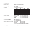
Marine Radio User Manual

3 - 1
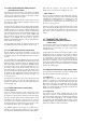
SECTION 3 DISASSEMBLY INSTRUCTIONS
A
B
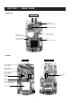
Chassis panel
C
E
E
D
Sealing rubber
J1
LOGIC unit
D
Chassis panel
F
F
LOGIC unit
F
Shield plate
•
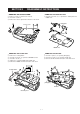
REMOVING THE CHASSIS PANEL
1 Remove 1 knob A, and unscrew 1 nut B.
2 Unscrew 2 screws C.
3 Remove the chassis panel in the direction of the arrow.
•
REMOVING THE LOGIC UNIT
1 Remove the sealing rubber.
2 Unsolder 1 point, D, to separate a SENSOR control.
3 Unscrew 3 screws, E.
4 Unplug J1 to separate LOGIC unit and RF unit.
5 Remove the LOGIC unit in the direction of the arrow.
•
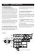
REMOVING THE RF UNIT
1 Unsolder 1 point, G, to separate [ANT] plug.
2 Unscrew 8 screws, H, to separate the RF unit.
3 Remove the RF unit in the direction of the thick arrow.
•
REMOVING THE SHIELD PLATE
1 Unsolder 10 points, F, to separate the shield plate and
LOGIC unit.
H
H
G
[ANT] plug
RF unit