
Laptop User Manual


6-20 Computer Group Literature Center Web Site
Functional Description
6
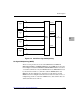
Front Panel Indicators (DS1 - DS3)
There are three LEDs on the MCPN750A front panel: BFL, CPU, and HOT
SWAP STATUS.
❏ BFL (DS1, yellow). Board Failure; lights when the BRDFAIL∗ signal
line is active.
❏ CPU (DS2, green). CPU activity; lights when the DBB∗ (Data Bus
Busy) signal line on the processor bus is active.
❏ HOT SWAP STATUS (DS3, blue). Lights when it is permissible to
extract the board.
MPC750 Processor
The MPC750 is a 64-bit processor with 64KB on-chip cache (32KB data
cache and 32KB instruction cache). The L2 cache is implemented with an
on-chip, two way set associative tag memory and with external
synchronous SRAMs for data storage. The minimum processor speed is
266 MHz. The maximum external processor bus speed is 66 MHz.
Processor data bus parity generation and check is supported in conjunction
with the Raven/Falcon chipset.
Raven PCI-Host Bridge
The Raven bridge controller ASIC provides the bridge between the
MPC750 microprocessor bus and the PCI local bus. Electrically, the Raven
chip is a 64-bit PCI connection. Four programmable map decoders in each
direction provide flexible addressing between the MPC750
microprocessor bus and the PCI local bus.
Flash Memory
The MCPN750A base board contains one bank of writeable Boot Flash
memory. It consists of two 32-pin PLCC sockets that can be populated
with 1MB of FLASH memory. This FLASH memory appears as FLASH
Bank B to the Falcon chipset. Only 8-bit writes are supported for this bank.