
Specifications


English LD-G-3 / LD-W-3
Page 32
Fixing the locomotive decoder
After completing all connections fix the locomotive decoder with double-
sided adhesive tape, for example.
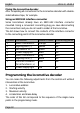
Using an NEM 652 interface connector
Some locomotives already have an NEM 652 interface connector
mounted. Using a convenient connecting plug you save disconnecting
the connections and you do not need to solder at the locomotive.
The list shows how to connect the contacts of the interface connector
to the connecting points of the locomotive decoder.
Contact Connection Colour of cable Connecting points
1 Motor connection 1 orange X10
2 Lighting back (-) yellow X4
3 Not used or F1 green ---
4 Power supply left black X3
5 Motor connection 2 grey X11
6 Lighting front (-) white X5
7 Common conductor
for all functions (+)
blue X6
8 Power supply right red X2
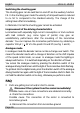
Programming the locomotive decoder
You can make the following adjustments from the central unit without
intervention at the locomotive:
1. Locomotive address
2. Starting velocity
3. Maximum velocity
4. Acceleration and brake delay
The order of this list corresponds to the sequence of the single menu
points in the programming mode.