n LD-W-1 n Lokdecoder für Wechselstrommotoren Motorola-Format n Locomotive Decoder for AC engines Motorola-Format n Décodeur pour locomotive avec moteur alternatif Format-Motorola n Locdecoder voor wisselstroommotoren Motorola-format n Art.-Nr.
© 08/2001 Tams Elektronik GmbH Alle Rechte, insbesondere das Recht der Vervielfältigung und Verbreitung sowie der Übersetzung vorbehalten. Vervielfältigungen und Reproduktionen in jeglicher Form bedürfen der schriftlichen Genehmigung durch die Tams Elektronik GmbH. Technische Änderungen vorbehalten. © 08/2001 Tams Elektronik GmbH All rights reserved.
English LD-G-1 / LD-W-1 Table of contents How to use this manual 21 Intended use 21 Safety instructions 22 EMC declaration 24 Information: Motorola I and Motorola II format 24 Operation overview 25 Checking the package contents 26 Technical specifications 26 Required tools and consumables 26 Safe and correct soldering 27 Performing a visual check 27 Mounting the locomotive decoder 28 Setting the locomotive decoder 31 Operation 32 FAQ 32 Manufacturer's note 33 Certification
LD-G-1 / LD-W-1 English How to use this manual If you have no specialist technical training, this manual gives step-bystep instructions for safe and correct fitting of the module, and operation. Before you start, we advise you to read the whole manual, particularly the chapter on safety instructions and the FAQ chapter. You will then know where to take care and how to prevent mistakes which take a lot of effort to correct. Keep this manual safely so that you can solve problems in the future.
English LD-G-1 / LD-W-1 Safety instructions Mechanical hazards Cut wires can have sharp ends and can cause serious injuries. Watch out for sharp edges when you pick up the PCB. Visibly damaged parts can cause unpredictable danger. Do not use damaged parts: recycle and replace them with new ones. Electrical hazards § Do not touch powered, live components. § Do not touch conducting components which are live due to malfunction. Avoid short circuits.
LD-G-1 / LD-W-1 English Fire risk Touching flammable material with a hot soldering iron can cause lifethreatening fire, burns and toxic smoke. Connect your soldering iron or soldering station only when actually needed. Use the correct soldering iron or station and never leave a hot soldering iron or station unattended. Thermal danger A hot soldering iron or liquid solder accidentally touching your skin can cause skin burns.
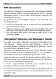
English LD-G-1 / LD-W-1 EMC declaration This product is developed in accordance with the European standards EN 55014 and EN 50082-1, tested corresponding to the EC - directive 89/336/EWG (EMVG of 09/11/1992, electromagnetic tolerance) and meets legal requirements. To guarantee the electromagnetic tolerance you must take the following precautions: § Connect the transformer only to an approved mains socket installed by an authorised electrician.
LD-G-1 / LD-W-1 English Operation overview The decoder is designed for operation in Motorola I or II format and can be adjusted to one of 255 adresses. It evaluates the digital data sent by the central unit to its address and transmitts it to the locomotive. Function speed level and direction of motion The speed level set at the central unit and the change-direction command are transmitted to the locomotive by the decoder.
English LD-G-1 / LD-W-1 Checking the package contents Check the contents of the package for completeness: § 1 module § 1 manual Technical specifications Data format Supply voltage Current consumption (without connected loads) Max. current for motor Max. current per function output Max. total current Protected to Ambient temperature in use Ambient temperature in storage Comparative humidity allowed Dimensions Weight Motorola I and II 12-22 Volt digital voltage ca. 10 mA 1.000 mA 500 mA 1.
LD-G-1 / LD-W-1 English Safe and correct soldering ! Caution: Incorrect soldering can cause fires (through excessive heat). Avoid this danger by reading the chapter Safety instructions again and following the directions given. If you have had training in soldering you can skip this chapter. § When soldering electronic circuits never use soldering-water or soldering grease. They contain acids that can corrode components and copper tracks. § Only use tin solder SN 60 Pb (i.e.
English LD-G-1 / LD-W-1 Mounting the locomotive decoder Open the locomotive housing. Locate the position for the decoder. Disconnect the motor from the rail current collector respectively the change-over switch from the motor and rails if you have a locomotive with electronic change-over switch. ! Caution: The interference suppression devices mounted to the motor or the connecting wire must not be removed! Motor and interference suppression devices are one unit.
LD-G-1 / LD-W-1 English Connecting the lighting and other accessories Follow the connections diagrams (fig. 3a and 3b)! Disconnect any existing diodes in the leads to the lamps. Connect the lamps for forward motion to X4 and the lamps for reverse to point X5 (front of the locomotive decoder). If the lamps are already connected with one side to locomotive ground, you must solder in a diode between the decoder and the lamp (see fig. 3a) or you must connect the second side of the lamps according to fig.
English ! LD-G-1 / LD-W-1 Caution: If you use light-emitting diodes (LEDs) you must always operate them via a series resistor. LEDs are available in many different models. There are LEDs with 2-5 mA, but also LEDs with 15-30 mA power consumption. The series resistor limits the current flow of the LED and will need to be calculated for each model. Ask for the max current rating when buying your LEDs. You can connect several LEDs in parallel to each output.
LD-G-1 / LD-W-1 English Some locomotives already have an NEM 652 interface connector mounted. Using a convenient connecting plug you save disconnecting the connections and you do not need to solder at the locomotive. The list shows how to connect the contacts of the interface connector to the connecting points of the locomotive decoder. Setting the locomotive decoder Setting the acceleration and brake delay The locomotive decoder can be set to one of three different delays: fast, medium or slow.
English ! LD-G-1 / LD-W-1 Caution: Use a soldering iron with a small tapered point and max. 30 Watt to make the solder bridges. Take special care to avoid short circuits. If necessary, check the solder bridges with a magnifiying glass to make sure that the solder bridges are closed correctly and solder has not short-circuited adjacent components or connections.
LD-G-1 / LD-W-1 English Possible cause: The connection of the motor is connected to locomotive ground. à Disconnect the connection from locomotive ground. § The locomotive lighting does not correspond to its direction of travel. Possible cause: The forward and backward light connections have been exchanged. à Check the connections. Possible cause: The connections of the motor to the points X11 and X12 have been exchanged. à Exchange the connections. § A lamp flickers (this is not a defect).
English LD-G-1 / LD-W-1 Certification This product conforms with the EC- directive 89/336/EWG on electromagnetic radiation and is therefore CE certified. Conditional warranty This product is guaranteed for two years. The warranty includes free repair if the problem is due to material failure or incorrect assembly of the module by us. We guarantee the quality of the components. Other claims are excluded. By law, we are not responsible for damages or secondary damages in connection with this product.
LD-G-1 / LD-W-1 Einstellung der Adresse / Adjusting the address Réglage de l’adresse / Instellen van het adres Beispiel: Einstellung der Adresse "107" Example: Adjusting the address "107" Exemple: Réglage de l´adresse "107" Voorbeeld: Instellen van adres "107" Adresse Lötfeld - Soldering field Address Plots d´une rangé Adresse Soldeerpunten Adres X14 X13 X16 X15 1 2-3 2-4 2-3 2-4 2 2-3 2-4 2-4 2-4 3 2-4 2-3 2-4 2-3 4 2-3 2-3 2-3 2-3 5 2-3 2-3 2-4 2-3 6 2-4 2-4 2-4 2-3 7 2-3 2-4 2-3 2-3 8 2-3 2-4 2-4 2-3 9
LD-G-1 / LD-W-1 Adresse Lötfeld - Soldering field Address Plots d´une rangé Adresse Soldeerpunten Adres X14 X13 X16 X15 41 --1-2 -42 1-2 1-2 1-2 -43 -1-2 --44 -1-2 1-2 -45 1-2 1-2 2-4 1-2 46 -1-2 2-3 1-2 47 -1-2 2-4 1-2 48 1-2 -2-4 -49 --2-3 -50 --2-4 -51 1-2 1-2 2-4 -52 -1-2 2-3 -53 -1-2 2-4 -54 2-4 2-4 2-4 1-2 55 2-3 2-4 2-3 1-2 56 2-3 2-4 2-4 1-2 57 2-4 2-3 2-4 -58 2-3 2-3 2-3 -59 2-3 2-3 2-4 -60 2-4 2-4 2-4 -61 2-3 2-4 2-3 -62 2-3 2-4 2-4 -63 1-2 2-4 1-2 1-2 64 -2-4 -1-2 65 -2-4 1-2 1-2 66 1-2 2-3 1-2 -
LD-G-1 / LD-W-1 Adresse Lötfeld - Soldering field Address Plots d´une rangé Adresse Soldeerpunten Adres X14 X13 X16 X15 113 2-4 1-2 2-3 2-4 114 2-4 1-2 2-3 2-3 115 2-4 -2-3 2-4 116 2-4 -2-3 2-3 117 1-2 1-2 2-3 2-4 118 1-2 1-2 2-3 2-3 119 1-2 -2-3 2-4 120 1-2 -2-3 2-3 121 2-4 1-2 -2-4 122 2-4 1-2 -2-3 123 --1-2 1-2 124 2-4 --2-3 125 1-2 1-2 -2-4 126 1-2 1-2 -2-3 127 1-2 --2-4 128 1-2 --2-3 129 2-4 1-2 2-3 1-2 130 2-4 1-2 2-3 -131 2-4 -2-3 1-2 132 2-4 -2-3 -133 1-2 1-2 2-3 1-2 134 1-2 1-2 2-3 -135 1-2 -2-3 1-
LD-G-1 / LD-W-1 Adresse Lötfeld - Soldering field Address Plots d´une rangé Adresse Soldeerpunten Adres X14 X13 X16 X15 185 2-3 -2-4 2-4 186 --2-4 2-4 187 2-3 -1-2 2-4 188 --1-2 2-4 189 2-3 -2-4 1-2 190 --2-4 1-2 191 2-4 2-3 2-3 2-4 192 2-4 --2-4 193 2-4 2-4 1-2 2-4 194 2-4 2-4 1-2 1-2 195 2-4 1-2 1-2 2-4 196 2-4 1-2 1-2 1-2 197 2-3 2-4 -2-4 198 2-3 2-4 -1-2 199 2-3 1-2 -2-4 200 2-3 1-2 -1-2 201 2-3 2-4 1-2 2-4 202 2-3 2-4 1-2 1-2 203 2-3 1-2 1-2 2-4 204 2-3 1-2 1-2 1-2 205 2-4 2-3 1-2 2-3 206 2-4 2-3 1-2 -
LD-G-1 LD-G-1 LD-G-1 Schaltplan Circuit diagram Schéma de principe Schakelschema n n n Fig.
LD-W-1 LD-W-1 LD-W-1 Schaltplan Circuit diagram Schéma de principe Schakelschema n n n Fig.
LD-G-1 / LD-W-1 LD-G-1 / LD-W-1 Anschlußplan 1 Connections 1 Plan de raccordement 1 Aansluit plan 1 n n n Fig.
LD-G-1 / LD-W-1 LD-G-1 / LD-W-1 Anschlußplan 2 Connections 2 Plan de raccordement 2 Aansluit plan 2 n n n Fig.
n n n Aktuelle Informationen und Tipps: Information and tips: Informations et conseils: Actuele informatie en tips: http://www.tams-online.de n n n n n n Garantie und Service: Warranty and service: Garantie et service: Garantie en service: n n Tams Elektronik GmbH Sievertstraße 22 D-30625 Hannover fon: 0049 (0)511 / 55 60 60 fax: 0049 (0)511 / 55 61 61 e-mail: modellbahn@tams-online.