n LD-W-1 n Lokdecoder für Wechselstrommotoren Motorola-Format n Locomotive Decoder for AC engines Motorola-Format n Décodeur pour locomotive avec moteur alternatif Format-Motorola n Locdecoder voor wisselstroommotoren Motorola-format n Art.-Nr.
© 11/2004 Tams Elektronik GmbH Alle Rechte, insbesondere das Recht der Vervielfältigung und Verbreitung sowie der Übersetzung vorbehalten. Vervielfältigungen und Reproduktionen in jeglicher Form bedürfen der schriftlichen Genehmigung durch die Tams Elektronik GmbH. Technische Änderungen vorbehalten. © 11/2004 Tams Elektronik GmbH All rights reserved.
LD-G-1 / LD-W-1 English Table of contents How to use this manual 32 Intended use 32 Safety instructions 32 EMC declaration Operation overview 34 35 Technical specifications 38 Checking the package contents 38 Required tools and materials 39 Safe and correct soldering 39 Mounting the locomotive decoder 40 Setting the address via solder bridges 43 Programming the locomotive decoder 43 Operation 54 FAQ 55 Manufacturer's note 55 Certification 56 Conditional warranty 56 Appendix
English LD-G-1 / LD-W-1 How to use this manual If you have no specialist technical training, this manual gives step-bystep instructions for safe and correct fitting of the module, and operation. Before you start, we advise you to read the whole manual, particularly the chapter on safety instructions and the FAQ chapter. You will then know where to take care and how to prevent mistakes which take a lot of effort to correct. Keep this manual safely so that you can solve problems in the future.
LD-G-1 / LD-W-1 English Electrical hazards § § § § § § Touching powered, live components, touching conducting components which are live due to malfunction, short circuits, connecting the circuit to another voltage than specified, impermissibly high humidity, condensation build up can cause serious injury due to electrical shock. Take the following precautions to prevent this danger: § § § § § § § Never perform wiring on a powered module.
English § LD-G-1 / LD-W-1 remove liquid solder with a thick wet rag or wet sponge from the soldering tip. Dangerous environments A working area that is too small or cramped is unsuitable and can cause accidents, fires and injury. Prevent this by working in a clean, dry room with enough freedom of movement. Other dangers Children can cause any of the accidents mentioned above because they are inattentive and not responsible enough.
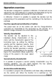
LD-G-1 / LD-W-1 English Operation overview The decoder is designed for operation in Motorola II format and can be adjusted to one of 255 addresses. It evaluates the digital data sent by the central unit to its address and transmits it to the locomotive. In Motorola I format it is possible to operate the decoder, but the programming of the parameters and the controlling of the functions is restricted.
English LD-G-1 / LD-W-1 acceleration and brake delay is deactivated (and simultaneously it switches over to the second velocity characteristic). Even if the acceleration and the brake delay are active you can actuate an emergency stop via the central unit by reversing the direction of travel. Automatic shuttle service If the automatic shuttle service is active the locomotive stops with the set brake delay as soon as the decoder detects a negative direct voltage on the track (Märklin* braking route).
LD-G-1 / LD-W-1 English Dimming: The function outputs X4 to X6 can be dimmed individually. Example of use: The electric bulbs of older locomotives made for analogue operation can be dimmed and thus must not be exchanged after the mounting of the decoder. Example of use: The front lighting is assigned to two different function outputs. Via one function key you can switch the standard lighting, via another the long distance lighting.
English LD-G-1 / LD-W-1 Restrictions in Motorola I format In Motorola I Format the following settings can be made: § § Address, starting and maximum velocity assignment of the funciton outputs to „function“ A reset and reading the address is not possible. It is not possible to program the second velocity characteristic or the acceleration and brake delay. The functions F1 to F4 cannot be switched. Technical specifications Data format Supply voltage Current consumption (without connected loads) Max.
LD-G-1 / LD-W-1 English Required tools and materials Make sure you have the following tools, equipment and materials ready for use: § § § § § § § § an electronic soldering iron (max. 30 Watt) with a fine tip, a soldering iron stand, a tip-cleaning sponge, a heat-resistant mat, a small side cutter and wire stripper, a pair of tweezers, tin solder (0,5 mm. diameter), wire (diameter: > 0,05 mm² for all connections).
English LD-G-1 / LD-W-1 Simultaneously add solder (not too much). As soon as the solder becomes liquid take it away. Hold the soldering tip at the spot for a few seconds so that the solder flows into the joint, then remove the soldering iron. The joint should be held still for about 5 seconds after soldering. A glossy and perfect soldering spot should remain. To make a good soldering joint you should use a clean and unoxidised soldering tip.
LD-G-1 / LD-W-1 English Connecting the LD-W-1 Follow the connections diagrams (fig. 1a and 2b)! Solder the connection to the slider at point X3 and the connection to the housing to point X2. These two connections can be exchanged without effecting functionality. Solder the connections to the motor at the points X11, X12 and X13. Connecting the lighting and other accessories Disconnect any existing diodes in the leads to the lamps.
English LD-G-1 / LD-W-1 X1), the load must be insulated. The loads should not make contact with metal parts of the locomotive. Possible short circuit! The locomotive decoder will be damaged in operation. ! Caution: The return conductor for all functions (point X1) must under no circumstances be connected to locomotive ground. Possible short circuit! The locomotive decoder will be damaged in operation.
LD-G-1 / LD-W-1 English You can connect up to 5 LEDs in parallel to each output. In this case every LED must have a series resistor of its own. If you connect several LEDs to one output in series, only one series resistor is needed. The number of LEDs connected in series to one output depends on the digital voltage.
English 7. 8. 9. 10. 11. 12.
LD-G-1 / LD-W-1 English You can finish the programming mode at any time by disconnecting the vehicle (pushing the button „stop“ or taking the vehicle from the track). Setting the locomotive address and the functions 1. Setting the locomotive address You are in the menu point „Setting the locomotive address“ when all lighting connected to the function outputs X4 to X6 flash regularly. Enter the desired address. You do not need to enter the old address.
English LD-G-1 / LD-W-1 Setting the dimming function: The dimming function is set via the speed knob. Speed level 0 stands for minimal voltage (if lamps are connected minimal brightness) at the output to be set and speed level 14 (250 on Märklin* Control Unit 6021) maximal voltage. Confirm your setting by switching the function key „function“ on and off once. Repeat the assignment of the function keys and the setting of the dimming function for the other two function outputs.
LD-G-1 / LD-W-1 English N.B. Some motors drive with a high PWM period more smoothly and consume less current (e.g. locomotives for large scales). On other motors a high PWM period has negative effects (e.g. high-performance engine). You should try which PWM period is the right one in the individual case. Setting the starting velocity: Operate the speed knob. As soon as the locomotive moves with the desired starting velocitiy, you should switch the function key „function” on and off once.
English LD-G-1 / LD-W-1 Then it brakes with the brake delay set at the speed knob. You may modify the brake delay by operating the speed knob. Speed level 0 corresponds to no brake delay, speed level 14 (250 on the Märklin* Control unit) to maximum brake delay. As soon as the brake delay is set as desired you have to confirm your setting by switching the function key „function“ on and off once. Setting the acceleration delay: Now switch on the auxiliary function F1.
LD-G-1 / LD-W-1 English Starting the programming mode Switch on the central unit or perform a reset at the central unit. Set address 78. Intellibox? YES For address 78: Set Motorola I format. NO Push button „stop“ à Switch off the track voltage. Operate the direction switch and hold it in that position. Briefly push the button „go“. As soon as the lighting flashes, release the direction switch. Intellibox? YES For address 78: Set Motorola II format.
English LD-G-1 / LD-W-1 Top menu level Setting the address and the functions. F3 Setting the driving characteristics. Disconnect the loco. F1 Querying the decoder address. Disconnect the loco. F2 Page 50 Performing a decoder reset. Closing the programming mode. Disconnect the loco.
LD-G-1 / LD-W-1 English Setting the locomotive address and the functions Assign the function keys: Switch on the function keys F1, F2, F3 and / or F4. Assign „function“: level 1: backward direction level 2: forward direction level 3: independent Enter the desired locomotive address.
English LD-G-1 / LD-W-1 Setting the driving characteristics step 1 For which characteristic ? 2 1 F4 „off“ function „on/off“ F4 „on“ Operate speed knob. Set maximum speed. Operate speed knob. Direction of travel o.k.? YES PWM high / low? HIGH F1 „on“ Page 52 Operate speed knob. Set starting speed. NO function „on/off“ F2 Operate direction switch.
LD-G-1 / LD-W-1 English Setting the driving characteristics step 2 Shuttle service on / off? OFF ON F3 „on“ F3 „off“ F1 „off“ Operate speed knob. Set brake delay. Level 0: No brake delay. Level 14: maximum brake delay. F1 „on“ Operate speed knob. Set acceleration delay. Level 0: No acceleration delay. Level 14: maximum acceleration delay. Disconnect the loco.
English LD-G-1 / LD-W-1 Operation Acceleration and brake delay / Second velocity characteristic In Motorola II format you can switch the acceleration and brake delay on or off and you can switch between the two velocity characteristics via F4. F4 off: Delay active and characteristic 1 set. The setting is immediately active. In Motorola I format you cannot switch the acceleration and brake delay on or off and you cannot switch to the second velocity characteristic.
LD-G-1 / LD-W-1 English FAQ § Parts are getting too hot and/or start to smoke. § Possible cause: one or more connections are soldered incorrectly. à Check the connections. Possible cause: The connection of the motor is connected to locomotive ground. à Disconnect the connection from locomotive ground. A lamp flickers (this is not a defect). § Possible cause: The lamp is connected with one side to locomotive ground.
English LD-G-1 / LD-W-1 Certification This product conforms with the EC- directive 89/336/EWG on electromagnetic radiation and is therefore CE certified. Conditions of warranty This product is guaranteed for two years. The warranty includes the correction of faults which can be proved to be due to material failure or factory flaw. We guarantee the adherence to the technical specifications of the circuit when assembled and connected according to the manual. Other claims are excluded.
LD-G-1 / LD-W-1 Tabelle: Rückmeldung der Decoderadresse Appendix: Check back of the address Tableau : Indiquation de l´adresse du décodeur Tabel: Terugmelding van het decoderadres Flash 1 * 1 1 1 1 1 1 1 1 1 1 1 1 1 1 1 1 2 2 2 2 2 2 2 2 2 2 2 2 2 2 2 2 Flash 2 * 1 2 3 4 5 6 7 8 9 10 11 12 13 14 15 16 1 2 3 4 5 6 7 8 9 10 11 12 13 14 15 16 Ad.
LD-G-1 / LD-W-1 Flash 1 * 5 5 5 5 5 5 5 5 5 5 5 5 5 5 5 5 6 6 6 6 6 6 6 6 6 6 6 6 6 6 6 6 7 7 7 7 Flash 2 * 1 2 3 4 5 6 7 8 9 10 11 12 13 14 15 16 1 2 3 4 5 6 7 8 9 10 11 12 13 14 15 16 1 2 3 4 Ad. ** 54 56 97 55 60 62 98 61 149 181 99 165 57 59 100 58 72 74 101 73 78 --102 79 150 182 103 166 75 77 104 76 194 202 105 198 Flash 1 * 7 7 7 7 7 7 7 7 7 7 7 7 8 8 8 8 8 8 8 8 8 8 8 8 8 8 8 8 Flash 2 * 5 6 7 8 9 10 11 12 13 14 15 16 1 2 3 4 5 6 7 8 9 10 11 12 13 14 15 16 Ad.
LD-G-1 / LD-W-1 Flash 1 * Flash 2 * Ad.
LD-G-1 / LD-W-1 Flash 1 * 14 14 14 14 14 14 14 14 14 14 14 14 14 14 14 14 15 15 15 15 15 15 15 15 * Flash 2 * 1 2 3 4 5 6 7 8 9 10 11 12 13 14 15 16 1 2 3 4 5 6 7 8 Ad. ** 45 47 133 46 51 53 134 52 158 190 135 174 48 50 136 49 196 204 137 200 220 228 138 224 Flash 1 * 15 15 15 15 15 15 15 15 16 16 16 16 16 16 16 16 16 16 16 16 16 16 16 16 Flash 2 * 9 10 11 12 13 14 15 16 1 2 3 4 5 6 7 8 9 10 11 12 13 14 15 16 Ad.
LD-G-1 / LD-W-1 LD-G-1 / LD-W-1 Fig.
LD-G-1 / LD-W- 1 LD-G-1 / LD-W- 1 Fig.
LD-G-1 / LD-W-1 LD-G-1 / LD-W-1 Fig.
n n n Aktuelle Informationen und Tipps: Information and tips: Informations et conseils: Actuele informatie en tips: http://www.tams-online.de n n n n n n Garantie und Service: Warranty and service: Garantie et service: Garantie en service: n n n Tams Elektronik GmbH Rupsteinstraße 10 D-30625 Hannover fon: +49 (0)511 / 55 60 60 fax: +49 (0)511 / 55 61 61 e-mail: modellbahn@tams-online.