
User manual


Definitions ST Assembler-Linker
54/89 Doc ID 11392 Rev 4
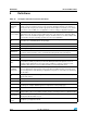
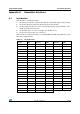
9 Definitions
Table 18. Acronyms and terms used in this document
Name Definition
Application
board
This is the printed circuit board onto which you wish to connect the target ST MCU. It should
include a socket or footprint so that you can connect the application board to your emulator or
development kit using the probe and the appropriate device adapter. This allows you to emulate
the behavior of the ST MCU in a real application in order to debug your application program.
Device adapter
Device adapters are included in your emulator kit to allow you to connect the emulator to your
application board. The type of device adapter depends on the target device’s packaging. Many
MCUs come in at least different packages, and you should therefore use the device adapter that
corresponds to the type of package you have chosen for your application.
DIL
Dual in line. Designates a type of device package with two rows of pins for thru-hole mounting.
Sometimes also called DIP (dual in-line package).
ECP Extended capabilities port communication standard.
EPP Enhanced parallel port communication standard.
LSB Least significant byte of a 16-bit value.
Main board
This is the main board of the emulator that is common to the entire ST HDS2 family of emulators.
It controls common functions such as communication with your PC via the parallel port.
mem Memory location.
mnem Mnemonic.
MCU
Microcontroller unit. Otherwise referred to as the target device throughout this manual. This is the
core product (or family of products) for which the Development Kit is designed to act as an
emulator and programming tool. In general terms, an MCU is a complete computer system,
including a CPU, memory, a clock oscillator and I/O on a single integrated circuit.
ST7MDT6-
active probe
A printed card having connector pins that allow you to connect the emulator to the MCU socket of
the user application board. Using the active probe allows the HDS2 emulator to function as if it
were the target device embedded in your application. The probe is connected to the emulator by
two flat cables.
PC
The program counter is the CPU register that holds the address of the next instruction or operand
that the CPU will use.
S Stack pointer LSB.
short Uses a short 8-bit addressing mode.
SO
Small outline. Designates a type of device package with two rows of pins for SMD or socket
mounting. For example, SO34 designates a 34-pin device of this package type.
src source
ST7 visual
debug (STVD7)
A graphic debugger software package that allows you to debug applications destined for the ST7
family of MCUs, either using a built-in simulator function, a Development Kit or an HDS2 Emulator.
Target device
This is the ST MCU that you wish to use in your application, and which your emulator or
development kit will emulate for you.
User application
board
Designates your application board.