Service Manual Level III ™ DIGITAL WIRELESS TELEPHONE TDMA M3090/M3097
COMPUTER SOFTWARE COPYRIGHTS The Motorola products described in this instruction manual may include copy-righted Motorola computer programs stored in semi-conductor memories or othermedia. Laws in the United States and other countries preserve for Motorola certain exclusive rights for copyrighted computer programs, including the exclusive right to copy or reproduce in any form the copyrighted computer program.
About This Manual Scope of Manual General Safety Information This manual is intended for use by experienced technicians familiar with similar types of equipment. It is intended primarily to support basic servicing, which consists primarily of mechanical repairs and circuit board replacement. Authorized distributors may opt to receive additional training to become authorized to perform limited component repairs. Contact your regional Customer Support Manager for details.
About This Manual TDMA M3090/M3097 lar telephone must be turned off to prevent any transmission. In standby mode, the mobile telephone will automatically transmit to acknowledge a call if it is not turned off. All equipment must be properly grounded according to installation instructions for safe operation. Portable/Mobile Telephone Use and Driving Safety is every driver’s business. The portable telephone should only be used in situations in which the driver considers it safe to do so.
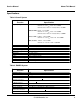
Service Manual About This Manual Specifications Table 1.Overall System Function Frequency Range Specification TX (800MHz) : 824.04 - 848.97 MHz Channels 1 to 799, fTX = 0.03 * N+ 825MHz Channels 990 to 1023, fTX = 0.03(N-1023)+ 825MHz RX(800 MHz): 869.04 – 893.97 MHz Channels 1 to 799, fRX = 0.03 * N+ 870MHz Channels 990 to 1023, fRX = 0.03(N-1023)+ 870MHz TX (1.9 GHz) : 1850.01 – 1909.95 MHz Channels 1 to 1999 fTX = 0.03 * N+ 1849.98MHz RX (1.9 GHz) : 1930.05 – 1989.
About This Manual TDMA M3090/T3097 Table 3. DAMPS System Function Modulation Type Frequency Stability Duty Cycle Error Vector Magnitude (π/4DQPSK mode) Transmit Audio Sensitivity Receive Sensitivity Adjacent and Alternate Channel Desensitization IM Vocoder Specification π/4DQPSK + 200 Hz 32.3% Error Vector Magnitude [Digital] 12.5% TOLR of –46 dB nominal -116 dBm for 3% static BER -116 dBm for 3% static BER Less than or equal to 3% static BER ACELP Table 4.
Table of Contents About This Manual ....................................................................................................................... iii Scope of Manual ....................................................................................................................... iii Model and Kit Identification ....................................................................................................... iii Service ..................................................................
Table of Contents TDMA M3090/M3097 Enter Programming Mode ............................................................................................................................ 24 Enter Security Code ..................................................................................................................................... 24 Enter Phone Number ...................................................................................................................................
Service Manual Table of Contents Communications Analyzer Setup: ................................................................................................................. 44 Setting up for PCS TDMA Measurements ................................................................................45 Power up the PCS Adapter, after two beeps are heard power up the 8920B ................................................. 45 Setting up for PCS TDMA Measurements ..............................................
Table of Contents TDMA M3090/M3097 Digital TX Audio Processing .....................................................................................................63 DSP Lucent 1629 .....................................................................................................................63 Stuart IC ...................................................................................................................................64 GCAP II .......................................................
Cellular Overview Introduction A cellular mobile telephone system divides the service area into small, low power radio frequency coverage areas called cells. A cellular system consists of a more or less continuous pattern of these cells, each having a 1 to 40 mile radius (typically 5 - 10 miles). Within each cell is a centralized cell site with an elevated antenna and a building. The building houses a base station with transceivers and related control equipment for the channels assigned to that cell.
Cellular Overview TDMA M3090/M3097 Introduction are defined in Figure 1. The cellular radio frequency spectrum has been divided by the FCC into two equal segments or bands to allow two independent cellular carriers to coexist and compete in the same geographic coverage area. Each band occupies one half of the available channels in the cellular spectrum.
Service Manual Cellular Overview Introduction naling required to establish a telephone call. Control channels are used to send and receive only digital data between the base station and the cellular telephone. Voice channels are used for both audio and signaling once a call is established. The 21 control channels in each band may be dedicated according to two different applications: access and paging channels.
Cellular Overview TDMA M3090/M3097 Introduction applications for each carrier. In 1987 the FCC expanded the cellular spectrum (Expanded Spectrum) from a total of 666 channels to 832 channels, allowing for an increase of 83 voice channels for each carrier. But the number of control channels remained constant, 21 control channels for each carrier.
Service Manual Cellular Overview Analog Cellular Analog Cellular central controller (switch). The simplified block diagram on page 1 - 7 illustrates an imaginary layout of one side (Band A, or Band B) of a hypothetical service area. The hexagons represent cells, and some of the cell sites shown here also illustrate the fact that an antenna tower and set of base stations are associated with each site.
Cellular Overview TDMA M3090/M3097 Analog Cellular the complement of the assigned DSAT. SAT (Supervisory Audio Tone) and DSAT (Digital SAT) The Supervisory Audio Tone (SAT) is one of three frequencies around 6 kHz used in AMPS signaling. On NAMPS channels SAT is replaced by one of seven sub-audible digital equivalents or vectors called DSAT.
Service Manual Cellular Overview Analog Cellular Analog Cellular Signal Summary (AMPS and NAMPS) The diagrams on the following pages outline the various uses of the signals employed in cellular systems. These signals include: SAT (Supervisory Audio Tone) 5970 Hz, 6000 Hz, or 6030 Hz. Used in AMPS for channel reuse, muting audio (squelch), and call continuation [typically ± 2 kHz deviation].
Cellular Overview TDMA M3090/M3097 Analog Cellular Total deviation of two or more signals is cumulative. Step 5. Decision point. Can the overhead message from the strongest control channel be decoded? If not, go to step 6. If it can be decoded go to step 8.* Step 6. The telephone tunes to the second strongest channel. Step 7. Decision point. Can the overhead message stream be decoded? If not, go to step 12. If it can be decoded, go to step 8.* Decision point.
Service Manual Cellular Overview Analog Cellular cessful completion of either steps 5 or 7, the telephone scans a set of paging channels, tunes to the strongest, and attempts to decode the overhead message train. The procedure is exactly equivalent to that followed for the access (control) channel. Also at this point, in a few larger systems, the telephone is commanded to identity itself (transmit) and thereby indicate its location in the system.
Cellular Overview TDMA M3090/M3097 Analog Cellular Placing a Call (Mobile to Land or Mobile to Mobile) When the cellular telephone user originates the call, the cellular telephone re-scans the access channels to assure that it is still tuned to the strongest one. The cellular tele- phone then transmits data at the rate of 10 kilobits per second on the control channel to notify the switch of its mobile identification number (MIN) and the number it wants to reach.
Service Manual Cellular Overview Analog Cellular The cellular telephone tunes to the assigned voice channel and verifies the presence of the proper forward SAT frequency (or DSAT message). If SAT (DSAT) is correct the telephone transponds SAT (DSAT) back to the cell site and unmutes the forward audio. The cell site detects reverse SAT (DSAT) from the cellular telephone and unmutes reverse audio.
Cellular Overview TDMA M3090/M3097 Figure 8. Land to Cellular Telephone Call Processing Landline Network The landline caller dials the cellular telephone number. The Public Service Telephone Network (central office) forwards the call to the central controller (switch). Switch / Cell Site Cellular Telephone DATA Overhead data is sent out on the control channels. FOCC & RECC The switch receives a call from land. The switch pages the cellular telephone.
Service Manual Cellular Overview Analog Cellular Power Steps As a call progresses, the cell site continuously monitors the reverse channel for signal strength. Every cellular telephone has a number of power steps ranging from full power (3 watts in a mobile and .6 watts in a portable) down to as low as about half a milliwatt. In reality all cellular telephones have eight power steps, but portable models are prevented from using the two highest power steps by the cell site.
Cellular Overview TDMA M3090/M3097 Figure 9. Cell Site Handoffs Cellular Telephone Switch / Cell Site Conversation in progress. The voice path is unmuted. VOICE + (D)SAT The cellular telephone acknowledges the handoff request by sending a10 kHz signaling tone for 50 msec or a DST message. The voice path is muted while sending ST. The telephone drops the voice channel and keys up on the new voice channel frequency. The telephone sends the newly assigned SAT (DSAT). Conversation in progress.
Service Manual Cellular Overview Analog Cellular Call Termination When the call is terminated by the landline caller (not the cellular telephone user), the central controller (switch) issues a release order to the subscriber unit. The cellular telephone acknowledges with a 10kHz signalling tone burst for 1.8 seconds and the cellular telephone ceases transmission. signalling tone burst for 1.8 seconds, indicating a call termination request to the switch.
Cellular Overview 16 TDMA M3090/M3097 ©1999 Motorola, Inc.
Service Manual Cellular Overview Digital Cellular Digital Cellular Multiplexing Using a single frequency to carry two or more communication links (e.g., conversations) is called multiplexing. There are two types of multiplexing that are feasible for cellular: code division multiplexing and time division multiplexing. Both code division multiplexing and time division multiplexing digitize voice before transmitting the signal.
Cellular Overview TDMA M3090/M3097 Digital Cellular line, such as that shown in the accompanying illustration, will be produced. audio. TDMA (Time Division Multiple Access) In the illustration on page 1 - 19 we saw how speech could be sampled at some rate. Suppose we take only one of every three samples. If our sampling rate is fast enough, and if we can compress the samples, it turns out that we can interleave several different conversations (communication links) on a single frequency.
Service Manual Cellular Overview Digital Cellular voice samples as viewed on oscilloscopes, are clearly shown to be nothing more than varying voltages produced by microphones. Instantaneous samples are discrete voltages. It has been shown that if the sampling rate is fast enough, it is possible to make a faithful representation of each conversation.
Cellular Overview TDMA M3090/M3097 Digital Cellular frequency. The IF is processed in the IF strip, which provides filtering and amplification. A discriminator retrieves audio from the IF and the varying voltages of the audio are used to drive a speaker TDMA Radio TDMA radios use the same circuitry as analog radios, for the most part, but also have additional circuitry to convert analog audio to digitized form and vice versa, and to select the appropriate time slot. Figure 16.
Accessories STANDARD TRAVEL CHARGER .................................................................................. SPN4474 • Charges battery in approximately 4-6 hours. • Provides power to your phone while simultaneously charging your battery. • Portable, small, and light enough to travel with. LEATHER CARRY CASE ............................................................................................... SYN7435 • Case helps protect phone’s surface from damage.
Accessories TDMA M3090/M3097 HANDS-FREE HEADSET (JEWEL CASE) .................................................................... SYN7453 • Enjoy simple hands-free operation. • One-piece design integrates microphone and earpiece. • Convenient pocket-sized case for easy portability and storage. HANDS-FREE HEADSET (BLUE POUCH) .................................................................... SYN6962 • Enjoy simple hands-free operation. • One-piece design integrates microphone and earpiece.
TDMA Easy NAM Programming Introduction The Number Assignment Module (NAM) is a section of memory that retains information about the phones characteristics, such as the assigned telephone number, system identification number, and options information. Two methods are available to program the NAM using the keypad: Test Mode and User Mode. Regardless of the method used, the NAM must be programmed before the phone can be placed into service.
TDMA Easy NAM Programming TDMA M3090/M3097 Programming Sequence Programming Sequence , carrier system ID (from your Cellular Service Enter Programming Mode Ê Press # Provider), # , * , snd . Phone displays " NAM 1 Prog * = Yes # = No". Ë Press * . Display prompts for Security Code "_ _ _ _ _ _". Enter Security Code Ì Press 0+ , 0+ , 0+ , 0+ , 0+ , 0+ (factory set). Phone displays ESN (Electronic Security Number). Í Press snd . Phone prompts for Phone Number " Phon # _ _ _ _ _ _ _ _ _ _".
TDMA Test Mode NAM Programming Introduction NAM Programming Steps The Number Assignment Module (NAM) is a section of memory that retains information about the phone’s characteristics, such as the assigned telephone number, system identification number, and options information. Two methods are available to program the NAM using the keypad: Test Mode and User Mode. There are 19 steps in the NAM. For each step, the display shows factory default NAM data.
TDMA Test Mode NAM Programming TDMA M3090/3097 NAM Data NAM Data NAM Data is specified by the system operator. For most NAM steps, the information specified by the system operator is the same as the factory default data. ferent from Test Mode NAM programming steps, and do not include all of the option bits available in Test Mode NAM programming. Access to User Mode NAM programming can be disabled by Test Mode NAM programming step 11, bit C7.
TDMA M3090/3097 TDMA Test Mode NAM Programming Test Mode NAM Programming Sequence * Advances to the next programming step; also programs the NAM after the last programming step is entered. CLR Clears the entered information and displays previously entered data for the current programming step. # Exits the programming mode without programming the NAM. Table 8.
TDMA Test Mode NAM Programming TDMA M3090/3097 Table 8: Test Mode NAM Programming Sequence (con’t) 07 000000 08 123 09 4 10 00000100 (B7-B0) 0 0 0 0 0 1 0 0 11 00001000 (C7-C0) 0 0 0 0 1 0 0 0 12 28 0334 Security code. A 6 digit number supplied by the user. This number is used by the user to access or change “security” features such as the 3-digit unlock code or the service level. Unlock code. A 3 digit number supplied by the user.
TDMA M3090/3097 TDMA Test Mode NAM Programming Table 8: Test Mode NAM Programming Sequence (con’t) 13 14 15 0333 0334 021 16 0737 17 18 19 0708 0737 10111011 1 0 1 1 1 0 1 1 Initial A system channel. To initialize system A enter 0333. Initial B system channel. To initialize system B enter 0334. Dedicated Paging Channels. Number of dedicated paging channels is 21. Enter 021. Secondary Initial Paging System. There are 3 significant bits for the secondary initial paging channel.
TDMA Test Mode NAM Programming 30 Motorola Confidential Proprietary TDMA M3090/3097
Manual Test Mode Introduction Status Display Level Manual Test Mode software allows service personnel to monitor the telephone status on the display, and manually control tele-phone functions via the keypad. Status Display level is the power-up state in manual test mode. In this level of manual test mode the phone will place and receive calls as normal, but the display shows two lines of status information.
Manual Test Mode TDMA M3090/M3097 Servicing Level Servicing Level The Servicing Level of Manual Test Mode allows service personnel to manually control operation of a phone by entering commands through the telephone keypad. Parameters such as operating channel, output power level, muting, and data trans-mission can all be selected by entering the corresponding commands.
TDMA M3090/M3097 Manual Test Mode Figure 17.
Manual Test Mode TDMA M3090/M3097 Figure 18.
Test Procedures Introduction The phone allows keypad controlled testing of various analog and digital operating parameters. This chapter includes the keypad button functions and recommended equipment setup to use when testing a phone. Automatic Call-Processing Tests Most communications analyzers can simulate a cell site in order to perform automatic call-processing tests. Automatic call processing tests can be performed while the phone is in its power-up state.
Test Procedures TDMA M3090/M3097 Test Connections The Zero Board test interface and an RF adapter with a low loss RF cable is used to interface with the communications analyzer. Test Connections The diagram below shows the recommended connections for PCS testing when using the HP83236B PCS Interface with the HP8920B via Serial Port. Make sure to set the HP-IB/ Ser switch of the HP-IB Address Selector on the rear panel of the PCS Interface to Ser. A variety of communications analyzers may be used.
Service Manual Test Procedures RF Cable Test RF Cable Test Figure 20. Duplex Test Screen DUPLEX TEST Tx Frequency Off Tx Power -0.62 Tune Mode Auto / Manual Tune Freq 834.990000 MHz Input Port RF In / Ant IF Filter 15 KHz Ext TX key On / Off dB dBm Rf Gen Freq 834.990000 MHz Amplitude 0.0 dBm Atten Hold On / Off Output Port RF Out / Dupl To test the RF cable for proper loss: AC Level Off SINAD AF Gen1 Freq 1.
Test Procedures TDMA M3090/M3097 Set up for Analog call Set up for Analog call Figure 21. Call Control Screen CALL CONTROL Display Data / Meas Phone : 111-111-1111 ESN (dec) : 156-4460397 ESN (hex) : 9C440F6 D SCM : Class IV, Continuous, 25 MHz Active Register Page Access Connect Active Register Page Handoff Release Order Chng PL 0 MS Id Phone Num 1111111111 Select CALL CNTL from the To Screen System Type DCCH Cntrl Chan 334 Tr affic Chan Assisgnment Chan : Pwr Lvl : - Amplitude -50.
Service Manual Test Procedures RX Sensitivity Test (SINAD) RX Sensitivity Test (SINAD) Figure 22. RX Test Screen Communications Analyzer Setup: RX TEST SINAD 8 AC Level dB 22.25 V 0.6336 24 -116.0 RF Gen Freq 879.990000 MHz AF Gen1 Freq 1 . 0000 kHz Amplitude -116.0 dBm Atten Hold On / Off AF Gen1 To FM 8.00 kHz Filter 1 C message AF Gen2 Freq 1 .
Test Procedures TDMA M3090/M3097 TX Power Out Test TX Power Out Test Figure 23. TX Test Screen TX TEST TX Frequency MHZ 834.9900 Tx Power 27.49 Tune Mode Auto / Manual Tune Freq 834.990000 MHz Tx Pwr Zero Zero KHz 11.58 AF Freq dBm KHz 1.00000 Input Port RF In / Ant AF Anl In FM Demod If Filter 230 KHz Filter 1 50 Hz HPF Ext TX Key On / Off Communications Analyzer Setup: FM Deviation dB Filter 2 15 KHz LPF AF Gen 1 Freq 1.0000 KHz AF Gen 1 Lvl 6.
Service Manual Test Procedures TX Frequency Error Test TX Frequency Error Test Figure 24. TX Test Screen TX TEST TX Frequency MHZ 834.9900 Tx Power 27.49 Tune Mode Auto / Manual Tune Freq 834.990000 MHz Tx Pwr Zero Zero KHz 11.58 AF Freq dBm KHz 1.00000 Input Port RF In / Ant AF Anl In FM Demod If Filter 230 KHz Filter 1 50 Hz HPF Ext TX Key On / Off Communications Analyzer Setup: FM Deviation dB Filter 2 15 KHz LPF AF Gen 1 Freq 1.0000 KHz AF Gen 1 Lvl 6.
TDMA M3090/M3097 Test Procedures TX Maximum Deviation Test TX Maximum Deviation Test Figure 25. TX Test Screen Communications Analyzer Setup: DUPLEX TEST Tx Frequency kHz dB FM Deviation Tx Power 25.2 Tune Mode Auto / Manual Tune Freq 834.990000 MHz Input Port RF In / Ant IF Filter 230 KHz Ext TX key On / Off Off 11.58 -0.199 dBm Rf Gen Freq 879.990000 MHz Amplitude -50.0 dBm Atten Hold On / Off Output Port RF Out / Dupl AF Freq Off 1.70000 AF Gen1 Freq 1.
Service Manual Test Procedures TX SAT Deviation Test TX SAT Deviation Test Figure 26. Call Control Screen Communications Analyzer Setup: DUPLEX TEST Tx Frequency kHz -0.199 Tx Power 25.2 Tune Mode Auto / Manual Tune Freq 834.990000 MHz Input Port RF In / Ant IF Filter 15 KHz Ext TX key On / Off d B dBm Rf Gen Freq 879.990000 MHz Amplitud e -50.0 dBm Atten Hold On / Off Output Port RF Out / Dupl FM Deviation Off 2.000 AF Freq Off 6.00000 AF Gen1 Freq 6.0000 kHz AFGen1 To FM 2.
Test Procedures TDMA M3090/M3097 TX ST Deviation Test TX ST Deviation Test Figure 27. TX Test Screen TX TEST TX Frequency MHZ 834.9900 Tx Power 27.49 Tune Mode Auto / Manual Tune Freq 834.990000 MHz Tx Pwr Zero Zero KHz 7.890 AF Freq dBm KHz 10.0000 Input Port RF In / Ant AF Anl In FM Demod If Filter 230 KHz Filter 1 50 Hz HPF Ext TX Key On / Off Communications Analyzer Setup: FM Deviation dB Filter 2 15 KHz LPF AF Gen 1 Freq 1.0000 KHz AF Gen 1 Lvl 6.
Service Manual Test Procedures Setting up for PCS TDMA Measurements Setting up for PCS TDMA Measurements Figure 31. Configure Screen RX/TX Cntl Auto / Manual Carrier / PTT RF Offset ON / Off (Gen) - (Anl) 0.000000 MHz RF Gen Volts 50 ohm / emf Range Hold Auto All Hold All State : Auto CONFIGURE RF Display Freq / Chan Intensity 8 Beeper Quiet RF Chan Std MS AMPS Low Battery 10 min User Def Base Freq. 800.000000 MHz Date 072099 MMDDYY RF Level Offset On / Off PCS RF I/O 0.0 dB TX-RX Offst 45.
Test Procedures TDMA M3090/M3097 Setting up for PCS TDMA Measurements Setting up for PCS TDMA Measurements Figure 30. DCCH Call Configure II Screen Num Voice 0 DCCH CALL CONFIGURE II Temperature Compensate Num SMS 0 MS Capab US PCS 5 In the MS Capab field select US PCS. Num Fax 0 Calling Num To Scre en RF GEN RF ANL AF ANL SCOPE SPEC ANL ENCODER DECODER RADIO INT SERVICE Calling Name Name Size 0 Pres Type Pres OK Screen Ind Not Scrn More Figure 31.
Service Manual Test Procedures Set up for TDMA call Set up for TDMA call Select CALL CNTL from the To Screen Figure 32.
Test Procedures TDMA M3090/M3097 MAHO Measurements MAHO Measurements Figure 33.
Service Manual Test Procedures BER Measurements BER Measurements Figure 35. Digital Measurements Screen BER Measurement Procedure DIGITAL MEASUREMENTS DTC Meas BER Arm Disarm Loopback BER % 2.8995 1 2 Bits Read: 10140 Amplitude -110.
Test Procedures TDMA M3090/M3097 TX Power Measurements TX Power Measurements Figure 36. Digital Measurements Screen DTC Meas Avg Power Digital TX Power Out Test Procedure DIGITAL MEASUREMENTS Average Power 1 dBm 24.1898 2 3 Amplitude -50.0 dBm TX Pwr Det CW Mode To Scre en Traffic Chan 333 Slot 1 CALL CNTL CALL CNFG ANLG MEAS SPEC ANL DIG MEAS DVCC 1 Trig Type 2X Frame More 4 5 6 7 Make sure the Test Set is in Active mode. Select DIG MEAS from the To Screen. Select the DTC Meas field.
Service Manual Test Procedures TX Frequency Error Measurements TX Frequency Error Measurements Figure 37. Digital Measurements Screen TX Frequency Error Measurement Test DTC Meas EVM 1 DIGITAL MEASUREMENTS Frequency Error kHz % EVM 0.0081 TX Power dB 3.9683 Peak EVM 11.6270 -2.35879 Amplitude -50.
Test Procedures TDMA M3090/M3097 EVM Measurements EVM Measurements Figure 38. Digital Measurements Screen DTC Meas EVM 1 Frequency Error kHz % EVM 3.9683 0.0081 TX Power dB Peak EVM % 11.6270 -2.35879 Amplitude -50.0 TX Frequency Error Measurement Test DIGITAL MEASUREMENTS 2 3 To Scre en Traffic Chan 333 dBm CALL CNTL Slot 1 Pwr Gain Auto / Hold 20 dB 1 CALL CNFG ANLG MEAS SPEC ANL DIG MEAS DVCC 1 Trig Type 2X Frame More 4 5 6 7 Make sure the Test Set is in Active mode.
Disassembly Introduction Some troubleshooting and maintenance procedures for cellular phones require disassembly of the phone to gain access to internal components. Reasonable care should be taken to avoid damaging or stressing the housing and internal components during disassembly and reassembly.
Disassembly TDMA M3090/M3097 Battery Removal Battery Removal 1. Turn off the telephone. 2. While holding the phone firmly with one hand, use the index finger on the other hand to press the latch on the battery cover. 3. Slide the cover back to release it from the phone. 4. Use the thumb and index finger to grab the battery and pull it out of the telephone housing.
Service Manual Disassembly Back Housing Removal Antenna Removal Use the thumb and index finger to remove the antenna using a counterclockwise twisting motion. Back Housing Removal 1. Using a T7 Torx driver, unscrew the five torx screw that attach the back housing to the main body of the phone. 2. Carefully lift the back housing and pull it off the main assembly.
Disassembly TDMA M3090/M3097 Transceiver Board Removal Transceiver Board Removal 1. While holding the phone firmly with one hand, use the thumb ,middle and index fingers of the other hand to carefully separate the transceiver phone from the main assembly. Display Removal 1. Using the tweezers, lift the clip that holds the flex cable in place. Remove the flex cable from the clip. 2. Lift the latches that hold the display in place to separate the display from the main board.
Service Manual Disassembly Speaker Removal 3. Carefully lift the display away from the main board. Keypad Removal 1. Lift the keypad from the front housing using the thumb and index fingers. Speaker Removal 1. Carefully pry off the speaker from the front housing using tweezers.
Disassembly 58 TDMA M3090/M3097 Motorola Confidential Proprietary
Parts List Introduction Mechanical Explosion Motorola maintains a parts office staffed to process parts orders, identify part numbers, and otherwise assist in the maintenance and repair of Motorola Cellular products. Orders for all parts listed in this document should be directed to the following Motorola International Logistics Department: The Mechanical explosion contains a table of mechanical part numbers that may change after publication of this manual.
60 Motorola Confidential Proprietary AAA BATTERY DOOR ALERT SCREWS 5 6 7 3 4 ANTENNA DISPLAY SPEAKER GASKET SPEAKER 1 2 6 8504892Z02 7204516Z02 3203997K01 5009150J04 5009005J09 0309315B02 SHN6842A 7 5 4 2 12 13 BATTERY AAA REAR HSG. MIC RF BOARD MYLAR KEYPAD AA BATTERY DOOR 3 8 9 10 11 1 7A Figure 39. Mechanical Explosion 4009410U04 3887349K01 5009536H15 N/A 0109482U06 SHN6841A SNN5366A 8 9 20 14 FRT.
General Description Antenna Circuit NADC IC Two RF ports are designed in this transceiver; internal antenna and external antenna. An RF switch controls which antenna path is going to be used during operation. Since this transceiver operates in two frequency bands(800MHz and 1900MHz), the switch also controls the RF frequency paths. Only one RF port and frequency band is used at a time, therefore, only one RF switch configuration is used while the other is irrevelent. The NADC/PDC ZIF/SYN is a 2.
General Description TDMA M3090/M3097 TX Operational Description TX Operational Description For the 800 Mhz band, the TX carrier frequency is generated by mixing the main VCO signal with the offset VCO.In analog mode, the Offset VCO is modulated to provide FM. In digital mode, the mixer output feeds an IQ modulator which is bypassed in analog mode.The signal passes through attenuators before being fed to the driver amplifier with bandpass filters and then it is sent to the 2 stage power amplifier.
Service Manual General Description DSP Lucent 1629 Digital TX Audio Processing Analog TX Audio Processing The analog voice signal coming in through the microphone is taken by the CODEC and digitized.The samples produced by this step are then sent to the DSP.The following steps are realized with software implementation: • Nominal TX Mic.
General Description TDMA M3090/M3097 Stuart IC Stuart IC GCAP II The STUART chip is a device intended for the following five functions. GCAP II is intended to provide audio and power management functions for Motorola cellular telephone applications. GCAP II is composed of two die.
Motorola Confidential Proprietary U701 U701 800MHz PA Coupler 800MHz Duplexer Coupler BPF Q1582 FL720 BPF Q830 X2 RX Front-end IC U101 Driver Amp BPF BPF Driver Amp RF Detect FL710 1900MHz PA U801 1900MHz Duplexer U801 RF Switch Figure 40. RF Block Diagram BPF Main VCO Loop Filter I IQ Mod Q TX Mod Offset VCO Synthesizer IF Receiver Custom IC U401 Modulator IC U601 BPF Loop Filter IF Filter 19.
Motorola Confidential Proprietary BOOM MIC HSET_DTCT B+ AUDIO IN BOOM OUT AUDIO OUT CHARGE CONTROL HEADSET DETECT CIRCUIT BATT+ BATT+ CHG- BATT_GND MAN_LVL CMP_LVL 3WB_RTN AGC_RSSI EXT_EN SW_EXT_B+ BATT_THERM BA TT DISCHG EXT_B+ DISCONNECT CIRCUIT MANTEST BATT FDBK AUDIO OUT B+ MICIN+ MICOUT MICIN- SPKRIN SPKR+ SPKROUT SPKRMIC_BIAS MB_CAP AUX_MICAUX_OUT EXT_MIC EXTOUT ALRTOUT ISENSE CHGRC AD0 AD1 AD2 AD3 AD4 AD5 WDI CE RESET VS IM VS IN VIN1 V1 VIN2 V2 VIN3 V3 LX2 PGND1
Service Manual Electrical Parts List Reference Designator Part Number Reference Designator Part Number Reference Designator Part Number A940 C1000 C1001 C1002 C1003 C1004 C1005 C1006 C101 C102 C104 C105 C106 C107 C108 C109 C110 C111 C112 C113 C114 C115 C116 C117 C118 C119 C120 C1200 C1201 C1202 C1203 C124 C1250 C1251 C126 C127 C130 C1300 C131 C139 C140 C1400 C1401 C1402 C1403 C1404 C1405 39-03918K01 21-13743M24 21-13741F49 21-13743E20 21-13743E20 21-13743M24 21-13743E20 21-13743M24 21-13743N40 21-1
Electrical Parts List A2 TDMA M3090/M3097 Reference Designator Part Number Reference Designator Part Number Reference Designator Part Number C159 C1590 C1591 C1592 C1593 C1594 C1595 C160 C1702 C177 C1900 C1901 C1902 C1903 C1904 C1905 C1906 C1907 C1908 C1914 C1915 C1916 C1917 C1918 C201 C202 C203 C204 C205 C206 C207 C260 C261 C301 C302 C303 C305 C306 C307 C310 C311 C312 C401 C402 C403 C404 C405 21-13743N40 21-13743N40 21-13743L05 21-13743N40 21-13743N40 21-13743N40 21-13743L09 21-13743N50 21-13743M
Service Manual Electrical Parts List Reference Designator Part Number Reference Designator Part Number Reference Designator Part Number C727 C729 C730 C731 C740 C741 C744 C758 C771 C777 C778 C801 C804 C805 C806 C807 C808 C809 C811 C812 C813 C816 C817 C820 C829 C830 C831 C833 C834 C835 C836 C840 C841 C888 C901 C902 C903 C904 C905 C906 C907 C908 C909 C910 C911 C912 C994 21-13743N24 21-13743N40 21-13743N40 21-13743N14 21-13743N40 21-13743N15 21-13743N15 21-13743E20 21-13743N28 21-13743N40 21-13743N28
Electrical Parts List A4 TDMA M3090/M3097 Reference Designator Part Number Reference Designator Part Number Reference Designator Part Number Q1100 Q1102 Q1200 Q1201 Q1300 Q1301 Q1302 Q1303 Q1304 Q1400 Q1401 Q151 Q152 Q1560 Q1570 Q1571 Q201 Q212 Q230 Q231 Q260 Q261 Q270 Q301 Q502 Q503 Q551 Q666 Q667 Q668 Q711 Q715 Q721 Q723 Q820 Q830 Q901 Q902 Q904 R1001 R1002 R1003 R1008 R1009 R1010 R1011 R1012 48-09579E29 48-09939C02 48-09605E02 48-09579E36 48-09579E29 48-09807C32 48-09579E29 48-09579E39 48-09939
Service Manual Electrical Parts List Reference Designator Part Number Reference Designator Part Number R202 R204 R205 R206 R207 R208 R209 R212 R255 R301 R302 R303 R304 R307 R310 R323 R352 R353 R414 R452 R453 R501 R503 R504 R505 R506 R507 R508 R509 R510 R511 R512 R601 R603 R621 R622 R623 R667 R668 R669 R670 R671 R673 R674 R675 R676 R677 06-62057M98 06-62057N17 06-62057N17 06-62057N16 06-62057M01 06-62057N11 06-62057M82 06-62057N15 06-62057N33 06-62057M92 06-62057N07 06-62057M94 06-62057M50 06-62057M01
Electrical Parts List A6 TDMA M3090/M3097 ©1999 Motorola, Inc.
Service Diagrams Introduction nections. The service diagrams were carefully prepared to allow a Motorola certified technician to easily troubleshoot cellular phone failures. Our professional staff provided directional labels, color coded traces, measurement values and other guidelines to help a technician troubleshoot a cellular phone with speed and accuracy. Because of the sensitivity of RF, measured readings will be greatly affected if they’re taken in certain locations.
TDMA M3090/M3097: Antenna Circuit U704 RF Switch Antenna RF Connector -5V FL931 800MHz FL930 1900MHZ V2 Q104 V1 TX_2.75 Q105 -5V 800*_1900 U104 800_1900* B2 Description Two RF ports are designed in this transceiver; internal antenna port and RF connector port. The RF switch (U704) controls which antenna path is going to be used during operation. Since this transceiver operates in two frequency bands (800MHz and 1900MHz), U704 also controls the RF frequency paths.
TDMA M3090/M3097: Antenna Circuit Band 800 1900 1900 800 Antenna Internal External Internal External 2.72V -4.6V -4.65V 2.69V E -4.65V 2.69V 2.72V -4.3V D 2.2V -4.15V -4.16V 2.18V G -4.15V 2.19V 2.21V -4.1V F Channel: 333 Cellular TX Freq: 834.99MHz PCS TX Freq: 1859.97MHz Cellular RX Input Freq: 879.99MHz PCS RX Input Freq: 1940.01MHz RX Input: -20dBm TX SIGNAL RX SIGNAL VOLTAGE SUPPLIES C777 F -5V page B29 C462 3 2 1 4 5 6 1 2 3 -5V page B29 TX_2.
TDMA M3090/M3097: Down Converter FL108 800*_1900 BAND_SW RX_800 FL140 U101 RX_1900 RX_2.75 VCO RX_IF DBLR_IN X2 VCC LO_CTL FE_EN B4 BUFF_VCO FL120 SW_QMOD_KEY Description The RX front end IC(U101) is used as a first amplifier and downconverter for dual-band RF applications. It removes the RX carrier frequency to produce the RX IF signal. U101 also has some internal LNAs for the receive signals and buffers for the VCO signals. U101 has two RF input ports.
TDMA M3090/M3097: Down Converter VCO R307 -9.27 dBm@Cellular 992.31MHz -9.35 dBm@PCS 1026.165MHz -26.8 dBm 1940.01MHz page B9 BUFF_VCO -30.47 dBm@Cellular 992.31MHz RX_2.75V In page B27 Motorola Confidential Proprietary Out -8.93 dBm 1940.01MHz C124 RX SIGNAL L140 VCO SIGNAL L141 Channel: 333 Cellular RX Input Freq: 879.99MHz PCS RX Input Freq: 1940.01MHz RX Input: -20dBm FL120 C605 page B13 This manual is Motorola property.
TDMA M3090/M3097: ZIF_SYNTH (U401) C401 RSSI IF Step Atten. U401 2nd LO Shifter U1000 SPI BUS DATA CLK CEX Offset LOOP SPI BUS 8/16/96 BIT MODES UP Converter VCO Offset VCO Demod DEMOD B6 Cap Filters Ref Osc Description MAIN LOOP AGC_RSSI LP_SWITCH 19.
TDMA M3090/M3097: ZIF_SYNTH (U401) This manual is Motorola property. Copying or distribution strictly prohibited without prior written consent from Motorola and must be returned upon Motorola's request. RX_SF TX_SF 5V page B27 RX_2.75V Motorola Confidential Proprietary -14.2 dBm@PCS 1026.165MHz page B27 U1903-56 page B41 U1903-55 page B41 U1903-57 page B41 U201-33 page B25 Q301,Q503 page B9 -15 dBm@Cellular 993.
TDMA M3090/M3097: VCO Q301A Filter Ckt. LP_SWITCH Q301B RX_SF VCO_STEER U301 MAIN_LO DBLR_IN VCO_FDBK B8 Description U301 is the local oscillator module used to add frequency selectivity to the transceiver. The frequency of oscillation is dependent on the channel and band that the transceiver will be operating in. The frequency is controlled by U401. U401 will receive channel information via the SPI bus and adjust the frequency of U301 by varying the voltage level to the input (VCO_STEER) of U301.
TDMA M3090/M3097: VCO This manual is Motorola property. Copying or distribution strictly prohibited without prior written consent from Motorola and must be returned upon Motorola's request. Channel: 333 PCS VCO Freq: 1026.165MHz Cellular VCO Freq: 993.31MHz VCO SIGNAL Motorola Confidential Proprietary VOLTAGE SUPPLIES Colored boxes represent the area in which the components are placed. U401 page B7 RXCP_ADA B LP_SWITCH U401 page B7 U401 page B7 VCO_STEER Channel A 991 333 799 A 1.19V 1.54V 1.
TDMA M3090/M3097: TX Offset Oscillator FM U201 DCI CR503 Q502 U401 ZIF-SYN IC TXCP_OUT TXCP_ADA LP_SWITCH B10 U1903 Loop Filter CR502 Tank Ckt U601 MERLIN TX Q503 800*_1900 C506 Q551 VCO_FDBK Description The offset oscillator frequency is controlled by U401(ZIF/SYN) via TXCP_OUT. The operating frequency will depend on the dc biasing of CR502. The offset oscillator frequency is 157.32MHz in 800MHz mode, and 192.36MHz in 1900MHz mode and is controlled by 800*_1900.
TDMA M3090/M3097: TX Offset Oscillator This manual is Motorola property. Copying or distribution strictly prohibited without prior written consent from Motorola and must be returned upon Motorola's request. Channel: 333 Cellular TX Input Freq: 157.32MHz PCS TX Offset Freq: 192.36MHz Motorola Confidential Proprietary TX SIGNAL Analog Digital VOLTAGE SUPPLIES A Colored boxes represent the area in which the components are placed. U401 page B7 LP_SWITCH 2.8V 0V Band 800 1900 2.1V 1.84V 0V 2.
TDMA M3090/M3097: MERLIN (U601) Main VCO U101 1900 U601 MERLIN FL620 U401 ZIFSYN Offset Osc U201 DCI XFMR601 FM FL601 TX_I TX_Q TX_STEP IQ Mod 800 AOC_CNTL B12 U1000 800*_1900 Description U601 is a TX modulator. It takes the TX information and modulates it on a carrier for RF transmission. In analog mode the offset oscillator with the FM enters U601 and gets mixed with the main VCO. The resulting signal is a differential carrier with the modulated information.
TDMA M3090/M3097: MERLIN (U601) Channel: 333 Cellular TX Freq: 834.99MHz PCS TX Freq: 1859.97MHz -21.5dBm 1859.97MHz VCO SIGNAL FL601 TX SIGNAL VOLTAGE SUPPLIES -30.47 dBm@800MHz 992.31MHz Colored boxes represent the area in which the components are placed. IN OUT This manual is Motorola property. Copying or distribution strictly prohibited without prior written consent from Motorola and must be returned upon Motorola's request. Motorola Confidential Proprietary XFMR601 -9.35 dBm@1.9GHz 1027.
TDMA M3090/M3097: Amp Drivers 800_KEY 800KEY* CR701-A Q230 800BIAS DRIVER_B+ Q711-A TX_800 FL720 Q715 TX_800 FL710 1900BIAS CR1561 1900_KEY CR701-B TX_2.75 1900KEY* TXENABLE Q666 PA_BIAS Q231 B14 800_CLAMP Q667 DRIVER_B+ CR666 1900_CLAMP Q711-B TX_1900 Q830 TX_1900 Description After the desired transmit information is modulated with a TX carrier frequency, enough signal power needs to be provided for RF transmission through the antenna.
TDMA M3090/M3097: Amp Drivers R682 page B17 R681 page B17 800_KEY B Motorola Confidential Proprietary C833 C D L831 R834 -24.87 dBm@PCS 1859.97MHz C830 C831 Q830 C835 L832 R830 page B17 C836 1900_BIAS 1900_OUT R712 R802 page B17 C840 page B13 CR701 L830 800KEY* R833 1900KEY* C834 U1903-62 page B41 A Q231 Q230 U1903-61 page B41 1900_KEY This manual is Motorola property.
TDMA M3090/M3097: PA Circuit (1900 MHz) 800KEY 800_ON PA_BIAS Q668B 1900KEY PA_BIAS TL920 Q668A 1900BIAS TX_1900 TL931 U801 TL930 B16 B+ Description DET_800_1900 TX_1900 1900_CLAMP Q820 The final stage PA circuit provides the necessary amount of power for RF transmission through an antenna. U801 is a PA module that is capable of operating in the 1900MHz band digital mode. Q820 controls the supply voltage to U801. The PA supply is sourced from the B+ line.
TDMA M3090/M3097: PA Circuit (1900MHz) R841 B+ Page B33 C805 1900 KEY L1552 B Page B19 Q667 PIN3 Page B15 E Q668 C808 R671 R802 14 6 R801 R681 Q721 PIN3 3 5 R839 800_ON 15 U801 VOLTAGE SUPPLIES Colored boxes represent the area in which the components are placed. 13 12 C817 Page B15 TX 1900 R831 C830 R682 Page B15 R830 2 4 C807 Q231 16 C812 Page B15 11 C811 A Channel: 333 TX Freq: 879.99MHz TX Power Level 2 TX SIGNAL C806 C804 Q230 800 KEY C841 R670 -3.
TDMA M3090/M3097: PA Circuit (800MHz) Q711-A 800_ON Q723 B+ 800BIAS Q721 800BIAS TX_800 A_D SWITCH PA_A_D R723 U701 Load B CR723 PA_A_D TL921 TL920 Load A TX_800 DET_800_1900 CR730 Q270 QMOD_KEY A_D SW_QMOD_KEY SW_QMOD_KEY TX_2.75 Q261 Description Q260 B18 A_D SWITCH The final stage PA circuit provides the necessary amount of power for RF transmission through an antenna. U701 is a PA module that is capable of operating in the 800MHz band under analog or digital mode.
TDMA M3090/M3097: PA Circuit (800MHz) Q668 PIN 4 This manual is Motorola property. Copying or distribution strictly prohibited without prior written consent from Motorola and must be returned upon Motorola's request. A 800_ON 3 14 U701 6 11 7 10 8 9 C731 CR730 R920 C741 Page B27 C261 TX_2.75 L730 R730 Q260 Q270 Q261 QMOD_KEY I R1915 Page B25 H C260 CR723 Page B25 U201-20 C158 Page B19 U201-14 PA_A_D E A_D F 0V G 1.98V 1.0V 0V 1.23V H C730 C Page B19 Q723 D 0.19V C 1.
TDMA M3090/M3097: RF Detect Circuit TX_STEP SW_QMOD_KEY Q902-A CR903 DET_800_1900 RF_DET TX_STEP TX_2.75 Q901 SW_QMOD_KEY Q902-B CR902 Q904 CR904 B20 Description The RF detect circuit is used to detect the RF amplitude level of the TX signal. RF detect reports back to U201 (DCI) pin 31, using a dc level, for amplitude stabilization. The RF detect circuit is RF coupled with the TX signal from either band, 800MHz or 1900MHz.
TDMA M3090/M3097: RF Detect Circuit R908 R206 Channel: 333 TX Freq: 879.99MHz TX Power Level 2 RF_DET B Page B25 VOLTAGE SUPPLIES C912 D C909 R907 R909 Page B17 L901 C903 Power Step 2 3 4 5 6 7 A 2.73V 2.73V 2.73V 2.73V 0V 0V B 1.23V .87V .63V .46V 1.36V .96V TX_STEP ON C 0.26V D 0.65V E 0.24V F 0.27V C905 R904 TX ON G 2.70V OFF 0.60V 0.06V 1.24V 2.71V OFF 0V C904 Q901 TX_2.75 Page B27 TX_STEP Page B19 This manual is Motorola property.
TDMA M3090/M3097: Reference Oscillator OSC_DIS RX_2.75 Q151 Q152 AFC 19.44MHZ U150 RF_19.44MHZ B22 Description The refere nce oscillator U150, operating at 19.44MHz, provides a "reference fre quency" fo r the RF synthesizers and various logic circuits. The OSC_DIS line which is controlled by U1000 (CPU) is used to turn off U150 during sleep mode. The OSC_DIS line switches Q151 on or off, controllin g the supply voltage to U150 and Q152. U201 (DCI) can "fine tune" U150 via the AFC line.
TDMA M3090/M3097: Reference Oscillator VOLTAGE SUPPLIES Colored boxes represent the area in which the components are placed. U1000 page B43 R151 OSC_DIS Q151 C151 RX_2.75V page B27 19.44MHz C153 C150 -11 dBm 19.44MHz B23 L150 R152 R153 AFC Q152 C160 C152 C414 page B7 R154 U150 U201-29 page B25 U1500,C1917 page B27 page B41 RF_19.44MHz This manual is Motorola property.
TDMA M3090/M3097: DCI (U201) BLOCK DIAGRAM NOT NECESSARY REFER TO PAGE B25 B24 Description The DCI (U201) is data converter interface between the DSP and the RF functions of a dual band T DMA transceiver.
TX On Off D 0V 3.77V G 0V 2.75V F 0V 2.76V TX_I U601 page B13 TX_IX U601 page B13 TDMA M3090/M3097: DCI(U201) C513 5.2Vpp@10kHz FM 440mV This manual is Motorola property. Copying or distribution strictly prohibited without prior written consent from Motorola and must be returned upon Motorola's request. page B11 U601 page B13 U601 page B13 2.
TDMA M3090/M3097: GCAP2 (U1500) BLOCK DIAGRAM NOT NECESSARY REFER TO PAGE B27 B26 Description The GCAP2(U1500) provides the regulators and start-up functions for the entire radio. The GCAP2 contains the following hardware blocks: • • • • • • • • • • • • • • On/Off control signals to properly activate the radio.
TDMA M3090/M3097: GCAP2(U1500) MICIN+ MICINALRTOUT MIC_OUT GCAP_INT 19.44MHz WDI MIC_OUT CR1500 U1000 page B43 C153 page B23 U1000 page B43 B+ page B33 R1588 page B37 C1505 5V ISENSE CHRGC AGC_RSSI CMP_LVL MAN_LVL RESET C1504 C1530 C1531 This manual is Motorola property. Copying or distribution strictly prohibited without prior written consent from Motorola and must be returned upon Motorola's request. Motorola Confidential Proprietary BATT_THERM R1591 2.
TDMA M3090/M3097: Voltage Regulators BATT_SAV Q1571 2.75V Q1570 -5V CR1420 5V -10V U1420 C1421 U1560 2.75V B28 VDOUB CR1560 Description There are some circuits that require a voltage higher than the battery source. For this reason, a voltage doubling charge pump circuit is provided. U1560 takes the 2.75V source and oscillates it with a high peak to peak signal. The positive region of the signal is then sent out to produ ced the VDOUB supply.
TDMA M3090/M3097: Voltage Regulators VOLTAGE SUPPLIES Colored boxes represent the area in which the components are placed. This manual is Motorola property. Copying or distribution strictly prohibited without prior written consent from Motorola and must be returned upon Motorola's request. Q1570 R1572 2.75V page B27 BATT_SAV Q1571 U201-16 page B25 Motorola Confidential Proprietary -5V 5V page B27 -10V C1420 C1575 U1560 C1423 CR1420 C1421 2.8Vpp@88.6kHz U1420 C1422 B29 5.2Vpp@13.
TDMA M3090/M3097: B+ Disconnect / Driver B+ EXT_B+ U1100 EXT_EN Q1102-A Q1102-B EXT_B+ SW_EXT_B+ Q1100 Driver_B+ U1590 V_Buck B30 Description The overvoltage circuit consist of a voltage detector (U1100) and a power switch(Q1100). A resistor divider network at the input of U1100 is used to set the EXT_B+ detect voltage to 9.2V nominal. U1100 outputs low when ever the input voltage is below the detector threshold.
TDMA M3090/M3097: B+ Disconnect/Driver B+ This manual is Motorola property. Copying or distribution strictly prohibited without prior written consent from Motorola and must be returned upon Motorola's request. C1517 C R1100 R1101 B VOLTAGE SUPPLIES Colored boxes represent the area in which the components are placed. EXT_EN U201-15 page B25 R1105 Off 3.77V D R1106 On 0V Q1102 D VR1100 TX >9.9V 3.48V 9.89V 2.87V R1103 Ext B+ <9.2V A 0V B 0V C 2.
TDMA M3090/M3097: Charger CR1300 B+ CHG- Q1301 R1305 SW_EXT_B+ Q1304A BATT+ Q1304B Q1303 SW_EXT_B+ R1300 BATT_FDBK ISENSE CHRGC BATT_FDBK_EN B32 BATT+ C1300 Q1302 SW_EXT_B+ BACKLIGHTING CR1301 BKLT Q1401 R1306 Q1400 Description The internal charger will be activated only when there is an external power source of 8.0V ± 0.4V for the fast charger, 7.05V ±0.35V for the midrate charger, a Motorola battery is attached, and BATT_FDBK is en abled.
TDMA M3090/M3097: CHARGER VOLTAGE SUPPLIES Colored boxes represent the area in which the components are placed. B+ This manual is Motorola property. Copying or distribution strictly prohibited without prior written consent from Motorola and must be returned upon Motorola's request. CHG- D Motorola Confidential Proprietary CR1300 J4 page B49 D F E BKLT C1300 R1302 R1305 Q1301 BATT+ page B49 SW_EXT_B+ G ISENSE page B31 R1300 R1306 Q1302 Backlight On Off A 2.71V 0V B 3.68V 5.4V C 0.
TDMA M3090/M3097: Audio/Data Communications BLOCK DIAGRAM NOT NECESSARY REFER TO PAGE B35 B34
TDMA M3090/M3097: Audio/Data Communications 1.2Vpp ALRTOUT C1556 U1500 page B27 PRE_REG U1500 page B27 ALER SPKRC1536 C1535 R1552 R1553 VR1552 U1500 page B27 page B27 1.2Vpp SPKR+ VR1551 R1555 R1554 VR1550 C1555 L1550 L1551 C1554 C1559 C1549 C1558 VR1553 1.2Vpp SPKR B35 SPKR T2 ALER T1 Channel: 333 Cellular RX Input Freq: 879.99MHz PCS RX Input Freq: 1940.01MHz RX Input: -20dBm This manual is Motorola property.
TDMA M3090/M3097: Headset/MIC HDST_SPKR AUX_OUT J8 AUX_MIC 2.75V R1560 BOOM_MIC_DET Q1560 B36 Description When a headset is inserted in J8, the internal speaker and microphone is disabled. The user can now use the headset for handsfree conversation. BOOM_MIC_DET informs U1000 whethe r a headset is inserted or not. The st ate of BOOM_MIC_DET is controlled by Q1 560. When the headset is inserted the biasing voltage for the AUX_MIC will no longer be present at the base of the NPN transistor Q1560.
TDMA M3090/M3097: Headset/MIC B Motorola Confidential Proprietary U1000 page B43 2.75V page B27 Q1560 R1560 C1560 C1563 C1562 A This manual is Motorola property. Copying or distribution strictly prohibited without prior written consent from Motorola and must be returned upon Motorola's request. Headset On Off A 0V 1.74V B 2.79V 0V 1.2Vpp TX AUDIO SIGNAL RX AUDIO SIGNAL VOLTAGE SUPPLIES J8 HDST_SPKR R1562 C1565 Channel: 333 Cellular RX Input Freq: 879.99MHz PCS RX Input Freq: 1940.
TDMA M3090/M3097: DSP (U1900) BLOCK DIAGRAM NOT NECESSARY REFER TO PAGE B39 Description B38 The following list is a description of the DSP(U1900): • • • • • • • • • ROM Mask Device(48K) Patch RAM space(16K) Fixed point MAC(multiply accumulator) 8-bit parallel interface 8-bit control I/O interface Dual serial I/O ports Two external interrupts Flexible power management including Sleep mode, Sleep with slow internal clock, and stop • • Three modes of operation • 1. Actively running 2.
TDMA M3090/M3097: DSP(U1900) VOLTAGE SUPPLIES U1903 page B41 MODEM_DATA U1500 page B27 CODEC_BUS U1903 page B41 MODEM_ADDR Colored boxes represent the area in which the components are placed. C1902 C1905 C1903 C1906 2.75V page B27 C1907 B39 U1900 C1900 R1900 2.75V page B27 INTEG_EN GP_INT DSP_TRAP TX RX SCLK FS RWN IO VDDA R1902 CLKI VPP CLK12 R1923 R1903 R1901 C1901 C1908 R1904 2.75V page B27 R1914 DSP_RST C153 page B23 19.
TDMA M3090/M3097: STUART (U1903) BLOCK DIAGRAM NOT NECESSARY REFER TO PAGE B41 B40 Description The STUART IC(U1903) is a custom gate array that uses the following func tions: Host Port Emulation - This provides a bus interconnection between the call processor and the DSP via the call processor’s parallel memory bus, interconnected to the modem DSP’s parallel memory bus.
TDMA M3090/M3097: STUART(U1903) This manual is Motorola property. Copying or distribution strictly prohibited without prior written consent from Motorola and must be returned upon Motorola's request. VOLTAGE SUPPLIES Motorola Confidential Proprietary Colored boxes represent the area in which the components are placed. Band 800 1900 B 0V C 0V D 2.73V 0V 0V 2.
TDMA M3090/M3097: Call Processor (U1000) BLOCK DIAGRAM NOT NECESSARY REFER TO PAGE B43 B42 Description U1000 is a single-chip microcontroller t hat controls major functions of the cellular phone. U1000 will perform the functions of both the master controller and keyboar d processor.
TDMA M3090/M3097: Call Processor(U1000) This manual is Motorola property. Copying or distribution strictly prohibited without prior written consent from Motorola and must be returned upon Motorola's request.
TDMA M3090/M3097: Memory WP* Q1200 R1201 U1200 B+ WP* Q1201 B44 Description A serial EEPROM(U1201) of 256K bytes is used for storage of the NAM information, authentication keys, phasing data, ESN, and memory. The EEPROM serial interface to the microcontroller is a standard SPI-compatible interface. U1250 is a 64K x 16 low voltage, low power SRAM. U1250 uses a parallel interface bus. U1200 is a 512K x 8 flash EPROM. U1200 uses a parallel interface bus.
TDMA M3090/M3097: MEMORY This manual is Motorola property. Copying or distribution strictly prohibited without prior written consent from Motorola and must be returned upon Motorola's request. Motorola Confidential Proprietary VOLTAGE SUPPLIES Colored boxes represent the area in which the components are placed. B+ page B33 R1203 Q1200 CALL_DATA U1000 page B43 CALL_ADD RAM_ENB B45 U1000 page B43 U1000 page B43 2.
TDMA M3090/M3097: Keypad BLOCK DIAGRAM NOT NECESSARY REFER TO PAGE B47 B46
TDMA M3090/M3097: Keypad This manual is Motorola property. Copying or distribution strictly prohibited without prior written consent from Motorola and must be returned upon Motorola's request. VOLTAGE SUPPLIES Colored boxes represent the area in which the components are placed. Motorola Confidential Proprietary Backlight A Off On 3.68V 5.
TDMA M3090/M3097: J7 Connector This manual is Motorola property. Copying or distribution strictly prohibited without prior written consent from Motorola and must be returned upon Motorola's request. Motorola Confidential Proprietary C1400 D5 D4 R/W A0 RESET R1412 2.
TDMA M3090/M3097: Layout Side 1 C1914 TP9 C817 C998 C909 R907 C905 R905 Q902 C908 C903 R904 CR901 C904 R902 C722 Q901 C701 C727 J950 C731 R723 Q723 R703 C726 R741 R701 FL930 Q904 R901 C910 L903 L701 Q721 C704 C703 R741 L902 CR902 L901 C709 C740 L740 C741 C261 R920 CR730 C730 R730 R621 R1915 Q260 Q270 Q261 CR723 L730 ALER R740 VR1552 FI D4 C112 C111 C177 VR1553 C127 C108 C105 R218 C107 FL140 FL931 T1 C1559 C1558 L101 C106 R906 C907 C709
R1555 R1554 C1555 VR1550 L1551 L1550 C1554 SEND DS1407 C1413 R1404 R1423 5 2 R1402 C104 C109 C994 C102 R1414 FCN R1412 DS1404 DS1411 R1422 R1411 R1413 # 9 6 3 R1428 C1407 C1408 C1409 C1412 R1410 Q1571 R1572 Q1570 DS1405 VOL_UP R1415 MESSAGE VOL_DOWN C1400 J_SPEAKER STO RCL DS1408 DS1409 8 0 DS1411 J1 CR130 R1302 C721 U104 C778 R1306 R1418 R1906 U704 Q1302 C720 DS1401 DS1400 C771 C1406 C777 C1402 C1403 C462 C1404 C1405 C995 R1417 C1401 R1300 B