
User manual
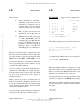
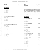

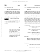
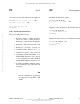
Table Of Contents
- COVER
- TABLE OF CONTENTS
- CHAPTER 1 GENERAL INFORMATION
- CHAPTER 2 DEBUG MONITOR DESCRIPTION
- CHAPTER 3 DEBUG MONITOR COMMANDS
- CHAPTER 4 ASSEMBLER/DISASSEMBLER
- CHAPTER 5 SYSTEM CALLS
- CHAPTER 6 DIAGNOSTIC FIRMWARE GUIDE
- APPENDIX A S-RECORD INFORMATION
- APPENDIX B SELF-TEST ERROR MESSAGES
- APPENDIX C USER CUSTOMIZATION
- LIST OF FIGURES
- LIST OF TABLES
- Table 2-1. Debugger Address Parameter Format
- Table 2-2. CPU32Bug Exception Vectors
- Table 3-1. Debug Monitor Commands
- Table 4-1. CPU32Bug Assembler Addressing Modes
- Table 5-1. CPU32Bug System Call Routines
- Table 6-1. MCU CPU Diagnostic Tests
- Table 6-2. Memory Diagnostic Tests
- Table B-1. Self-Test Error Messages
- Table C-1. CPU32Bug Customization Area
- Table C-2. MCU SCI Communication Formats
- Table C-3. Rev. A Chip Selection Summary
- Table C-4. Rev. B Chip Selection Summary
- Table C-5. BCC Rev. C Chip Selection Summary
- Table C-6. PFB Rev. C Compatibility
- CHAPTER 1 GENERAL INFORMATION
- CHAPTER 2 DEBUG MONITOR DESCRIPTION
- CHAPTER 3 DEBUG MONITOR COMMANDS
- 3.1 INTRODUCTION
- 3.2 BLOCK OF MEMORY COMPARE
- 3.3 BLOCK OF MEMORY FILL
- 3.4 BLOCK OF MEMORY MOVE
- 3.5 BREAKPOINT INSERT/DELETE
- 3.6 BLOCK OF MEMORY SEARCH
- 3.7 BLOCK OF MEMORY VERIFY
- 3.8 DATA CONVERSION
- 3.9 DUMP S-RECORDS
- 3.10 GO DIRECT (IGNORE BREAKPOINTS)
- 3.11 GO TO NEXT INSTRUCTION
- 3.12 GO EXECUTE USER PROGRAM
- 3.13 GO TO TEMPORARY BREAKPOINT
- 3.14 HELP
- 3.15 LOAD S-RECORDS FROM HOST
- 3.16 MACRO DEFINE/DISPLAY/DELETE
- 3.17 MACRO EDIT
- 3.18 MACRO EXPANSION LISTING ENABLE/DISABLE
- 3.19 MEMORY DISPLAY
- 3.20 MEMORY MODIFY
- 3.21 MEMORY SET
- 3.22 OFFSET REGISTERS DISPLAY/MODIFY
- 3.23 PRINTER ATTACH/DETACH
- 3.24 PORT FORMAT
- 3.25 REGISTER DISPLAY
- 3.26 COLD/WARM RESET
- 3.27 REGISTER MODIFY
- 3.28 REGISTER SET
- 3.29 SWITCH DIRECTORIES
- 3.30 TRACE
- 3.31 TRACE ON CHANGE OF CONTROL FLOW
- 3.32 TRANSPARENT MODE
- 3.33 TRACE TO TEMPORARY BREAKPOINT
- 3.34 VERIFY S-RECORDS AGAINST MEMORY
- CHAPTER 4 ASSEMBLER/DISASSEMBLER
- CHAPTER 5 SYSTEM CALLS
- 5.1 INTRODUCTION
- 5.2 SYSTEM CALL ROUTINES
- 5.2.1 Calculate BCD Equivalent Specified Binary Number
- 5.2.2 Parse Value, Assign to Variable
- 5.2.3 Check for Break
- 5.2.4 Timer Delay Function
- 5.2.5 Unsigned 32 x 32 Bit Divide
- 5.2.6 Erase Line
- 5.2.7 Input Character Routine
- 5.2.8 Input Line Routine
- 5.2.9 Input Serial Port Status
- 5.2.10 Unsigned 32 x 32 Bit Multiply
- 5.2.11 Output Character Routine
- 5.2.12 Output String Using Pointers
- 5.2.13 Print Carriage Return and Line Feed
- 5.2.14 Read Line to Fixed-Length Buffer
- 5.2.15 Read String Into Variable-Length Buffer
- 5.2.16 Return to CPU32Bug
- 5.2.17 Send Break
- 5.2.18 Compare Two Strings
- 5.2.19 Timer Initialization
- 5.2.20 Read Timer
- 5.2.21 Start Timer at T=0
- 5.2.22 Output String with Data
- 5.2.23 Output String Using Character Count
- CHAPTER 6 DIAGNOSTIC FIRMWARE GUIDE
- 6.1 INTRODUCTION
- 6.2 DIAGNOSTIC MONITOR
- 6.2.1 Monitor Start-Up
- 6.2.2 Command Entry and Directories
- 6.2.3 Help (HE)
- 6.2.4 Self Test (ST)
- 6.2.5 Switch Directories (SD)
- 6.2.6 Loop-On-Error Mode (LE)
- 6.2.7 Stop-On-Error Mode (SE)
- 6.2.8 Loop-Continue Mode (LC)
- 6.2.9 Non-Verbose Mode (NV)
- 6.2.10 Display Error Counters (DE)
- 6.2.11 Clear (Zero) Error Counters (ZE)
- 6.2.12 Display Pass Count (DP)
- 6.2.13 Zero Pass Count (ZP)
- 6.3 UTILITIES
- 6.4 CPU TESTS FOR THE MCU
- 6.5 MEMORY TESTS (MT)
- 6.6 BUS ERROR TEST
- APPENDIX A S-RECORD INFORMATION
- APPENDIX B SELF-TEST ERROR MESSAGES
- APPENDIX C USER CUSTOMIZATION
DEBUG MONITOR COMMANDS
M68CPU32BUG/D REV 1 3-50
PF Port Format PF
( the next response demonstrates reversing the prompting order )
XON/XOFF protocol [Y,N] = Y? ^ <CR> Backup
Stop Bits [1,2] = 2? .<CR> Value acceptable, exit interactive
mode.
OK to proceed (y/n)? Y Note: Carriage return not required.
CPU32Bug>
3.24.3 Port Format Parameters
The port format parameters are:
• Port base address – When assigning a port, there is a set base address option. This
allows the user to adjust the base address for different hardware configurations.
Entering no value selects the default address.
• Baud rate – Select the baud rate: 110, 300, 600, 1200, 2400, 4800, 9600, 19200.
• Parity type – Set parity: even (E), odd (0), or disabled (N).
• Character width – Select 5-, 6-, 7-, or 8-bit characters.
• Number of stop bits – Only 1 and 2 stop bits are supported.
• Automatic software handshake – Current drivers have the capability of responding to
XON/XOFF characters sent to the debugger ports. Receiving a XOFF causes a driver
to cease transmission until a XON character is received. None of the current drivers
utilize FIFO buffering, therefore, none initiate an XOFF condition.
• Software handshake character values – The values used by a port for XON and XOFF
may be defined as any 8-bit value. ASCII control characters or hexadecimal values are
accepted.
NOTE
Not all combinations of parity type, character width, and stop bits
are supported for the BCC "SCI" port, 00. See Appendix C for
details.
DEBUG MONITOR COMMANDS
M68CPU32BUG/D REV 1 3-47
OF Offset Registers Display/Modify OF
Set R0 as the automatic register.
CPU32Bug>OF R0;A<CR>
R0*=00005000 000050FF? .<CR>
Display location 0 relative to the default offset register, (R0), i.e. absolute location $5000.
CPU32Bug>M 0;DI<CR>
00000+R0 41F95445 5354 LEA.L ($54455354).L,A0 .<CR>
CPU32Bug>
Display absolute location 0, override the automatic offset.
CPU32Bug>M 0+R7;DI <CR>
00000000 FFF8 DC.W $FFF8 .<CR>
CPU32Bug>
Fr
eescale S
emiconduct
or
, I
Freescale Semiconductor, Inc.
For More Information On This Product,
Go to: www.freescale.com
nc...