
User manual


Table Of Contents
- COVER
- TABLE OF CONTENTS
- CHAPTER 1 GENERAL INFORMATION
- CHAPTER 2 DEBUG MONITOR DESCRIPTION
- CHAPTER 3 DEBUG MONITOR COMMANDS
- CHAPTER 4 ASSEMBLER/DISASSEMBLER
- CHAPTER 5 SYSTEM CALLS
- CHAPTER 6 DIAGNOSTIC FIRMWARE GUIDE
- APPENDIX A S-RECORD INFORMATION
- APPENDIX B SELF-TEST ERROR MESSAGES
- APPENDIX C USER CUSTOMIZATION
- LIST OF FIGURES
- LIST OF TABLES
- Table 2-1. Debugger Address Parameter Format
- Table 2-2. CPU32Bug Exception Vectors
- Table 3-1. Debug Monitor Commands
- Table 4-1. CPU32Bug Assembler Addressing Modes
- Table 5-1. CPU32Bug System Call Routines
- Table 6-1. MCU CPU Diagnostic Tests
- Table 6-2. Memory Diagnostic Tests
- Table B-1. Self-Test Error Messages
- Table C-1. CPU32Bug Customization Area
- Table C-2. MCU SCI Communication Formats
- Table C-3. Rev. A Chip Selection Summary
- Table C-4. Rev. B Chip Selection Summary
- Table C-5. BCC Rev. C Chip Selection Summary
- Table C-6. PFB Rev. C Compatibility
- CHAPTER 1 GENERAL INFORMATION
- CHAPTER 2 DEBUG MONITOR DESCRIPTION
- CHAPTER 3 DEBUG MONITOR COMMANDS
- 3.1 INTRODUCTION
- 3.2 BLOCK OF MEMORY COMPARE
- 3.3 BLOCK OF MEMORY FILL
- 3.4 BLOCK OF MEMORY MOVE
- 3.5 BREAKPOINT INSERT/DELETE
- 3.6 BLOCK OF MEMORY SEARCH
- 3.7 BLOCK OF MEMORY VERIFY
- 3.8 DATA CONVERSION
- 3.9 DUMP S-RECORDS
- 3.10 GO DIRECT (IGNORE BREAKPOINTS)
- 3.11 GO TO NEXT INSTRUCTION
- 3.12 GO EXECUTE USER PROGRAM
- 3.13 GO TO TEMPORARY BREAKPOINT
- 3.14 HELP
- 3.15 LOAD S-RECORDS FROM HOST
- 3.16 MACRO DEFINE/DISPLAY/DELETE
- 3.17 MACRO EDIT
- 3.18 MACRO EXPANSION LISTING ENABLE/DISABLE
- 3.19 MEMORY DISPLAY
- 3.20 MEMORY MODIFY
- 3.21 MEMORY SET
- 3.22 OFFSET REGISTERS DISPLAY/MODIFY
- 3.23 PRINTER ATTACH/DETACH
- 3.24 PORT FORMAT
- 3.25 REGISTER DISPLAY
- 3.26 COLD/WARM RESET
- 3.27 REGISTER MODIFY
- 3.28 REGISTER SET
- 3.29 SWITCH DIRECTORIES
- 3.30 TRACE
- 3.31 TRACE ON CHANGE OF CONTROL FLOW
- 3.32 TRANSPARENT MODE
- 3.33 TRACE TO TEMPORARY BREAKPOINT
- 3.34 VERIFY S-RECORDS AGAINST MEMORY
- CHAPTER 4 ASSEMBLER/DISASSEMBLER
- CHAPTER 5 SYSTEM CALLS
- 5.1 INTRODUCTION
- 5.2 SYSTEM CALL ROUTINES
- 5.2.1 Calculate BCD Equivalent Specified Binary Number
- 5.2.2 Parse Value, Assign to Variable
- 5.2.3 Check for Break
- 5.2.4 Timer Delay Function
- 5.2.5 Unsigned 32 x 32 Bit Divide
- 5.2.6 Erase Line
- 5.2.7 Input Character Routine
- 5.2.8 Input Line Routine
- 5.2.9 Input Serial Port Status
- 5.2.10 Unsigned 32 x 32 Bit Multiply
- 5.2.11 Output Character Routine
- 5.2.12 Output String Using Pointers
- 5.2.13 Print Carriage Return and Line Feed
- 5.2.14 Read Line to Fixed-Length Buffer
- 5.2.15 Read String Into Variable-Length Buffer
- 5.2.16 Return to CPU32Bug
- 5.2.17 Send Break
- 5.2.18 Compare Two Strings
- 5.2.19 Timer Initialization
- 5.2.20 Read Timer
- 5.2.21 Start Timer at T=0
- 5.2.22 Output String with Data
- 5.2.23 Output String Using Character Count
- CHAPTER 6 DIAGNOSTIC FIRMWARE GUIDE
- 6.1 INTRODUCTION
- 6.2 DIAGNOSTIC MONITOR
- 6.2.1 Monitor Start-Up
- 6.2.2 Command Entry and Directories
- 6.2.3 Help (HE)
- 6.2.4 Self Test (ST)
- 6.2.5 Switch Directories (SD)
- 6.2.6 Loop-On-Error Mode (LE)
- 6.2.7 Stop-On-Error Mode (SE)
- 6.2.8 Loop-Continue Mode (LC)
- 6.2.9 Non-Verbose Mode (NV)
- 6.2.10 Display Error Counters (DE)
- 6.2.11 Clear (Zero) Error Counters (ZE)
- 6.2.12 Display Pass Count (DP)
- 6.2.13 Zero Pass Count (ZP)
- 6.3 UTILITIES
- 6.4 CPU TESTS FOR THE MCU
- 6.5 MEMORY TESTS (MT)
- 6.6 BUS ERROR TEST
- APPENDIX A S-RECORD INFORMATION
- APPENDIX B SELF-TEST ERROR MESSAGES
- APPENDIX C USER CUSTOMIZATION
GENERAL INFORMATION
M68CPU32BUG/D REV 1 1-2
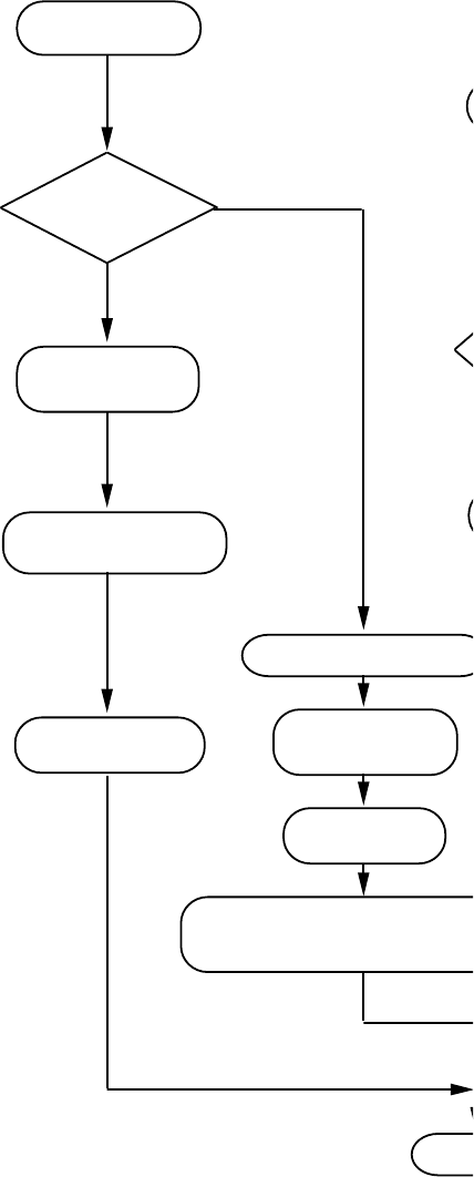
POWER-UP/RESET
WARM START?
SET DEBUGGER
DIRECTORY
DISPLAY DEBUGGER
NAME AND VERSION
DISPLAY WARM
START MESSAGE
YES
DISPLAY DEBUGGER NAME & VERSION
DISPLAY RESULTS OF CONFIDENCE
TEST
GO TO MAIN
SET DEBUGGER
DIRECTORY
INITILIZE BUG VARIBLES
RUN SYSTEM
CONFIDENCE TEST
NO
MAIN
DISPLAY BUG PROMPT
WAIT FOR INPUT
EXECUTE COMMAND
GO TO MAIN
RESTORE
TARGET STATE
TARGET CODE
EXECPTION
EXCEPTION
HANDLERS
SAVE TARGET
STATE
DISPLAY TARGET
REGISTERS
YES
NO
DOES COMMAND
CAUSE TARGET CODE
EXECUTION
Figure 1-1. CPU32Bug Operation Mode Flow Diagram
GENERAL INFORMATION
M68CPU32BUG/D REV 1 1-3
1.3 USING THIS MANUAL
Those users unfamiliar with debugging packages should read Chapter 1 before attempting to use
CPU32Bug. This provides information about CPU32Bug structure and capabilities.
Paragraph 1.4 Installation and Start-up describes a step-by-step procedure for powering up the
module and obtaining the CPU32Bug prompt on the terminal screen.
For questions about syntax or operation of a particular CPU32Bug command, turn to the
paragraph which describes that particular command in Chapter 3.
Some debugger commands take advantage of the built-in one-line assembler/disassembler. The
command descriptions in Chapter 3 assume that the user is familiar with the
assembler/disassembler functionality. Chapter 4 includes a description of the assembler/
disassembler.
NOTE
In the examples shown, all user inputs are given in bold text. This should clarify
the examples by distinguishing between character input by the user and character
output by CPU32Bug. The symbol <CR> represents the carriage return key on the
user’s terminal keyboard. Whenever this symbol appears it indicates a carriage
return should be entered by the user.
1.4 INSTALLATION AND START-UP
Use the following set-up procedure to enable CPU32Bug to operate with the BCC:
1. Configure the jumpers on the BCC module. Refer to the EVK User’s Manual
Motorola publication number M68332EVK/AD1 or M68331EVK/AD1.
2. Connect the DB-9 serial communication cable connector to the terminal or host
computer which is to be the CPU32Bug system console. Connect the other end of the
cable to P4 on the BCC.
Set up the terminal as follows:
• Eight bits per character
• One stop bit per character
• Parity disable
• 9600 baud rate
Fr
eescale S
emiconduct
or
, I
Freescale Semiconductor, Inc.
For More Information On This Product,
Go to: www.freescale.com
nc...