
User manual


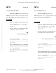

Table Of Contents
- COVER
- TABLE OF CONTENTS
- CHAPTER 1 GENERAL INFORMATION
- CHAPTER 2 DEBUG MONITOR DESCRIPTION
- CHAPTER 3 DEBUG MONITOR COMMANDS
- CHAPTER 4 ASSEMBLER/DISASSEMBLER
- CHAPTER 5 SYSTEM CALLS
- CHAPTER 6 DIAGNOSTIC FIRMWARE GUIDE
- APPENDIX A S-RECORD INFORMATION
- APPENDIX B SELF-TEST ERROR MESSAGES
- APPENDIX C USER CUSTOMIZATION
- LIST OF FIGURES
- LIST OF TABLES
- Table 2-1. Debugger Address Parameter Format
- Table 2-2. CPU32Bug Exception Vectors
- Table 3-1. Debug Monitor Commands
- Table 4-1. CPU32Bug Assembler Addressing Modes
- Table 5-1. CPU32Bug System Call Routines
- Table 6-1. MCU CPU Diagnostic Tests
- Table 6-2. Memory Diagnostic Tests
- Table B-1. Self-Test Error Messages
- Table C-1. CPU32Bug Customization Area
- Table C-2. MCU SCI Communication Formats
- Table C-3. Rev. A Chip Selection Summary
- Table C-4. Rev. B Chip Selection Summary
- Table C-5. BCC Rev. C Chip Selection Summary
- Table C-6. PFB Rev. C Compatibility
- CHAPTER 1 GENERAL INFORMATION
- CHAPTER 2 DEBUG MONITOR DESCRIPTION
- CHAPTER 3 DEBUG MONITOR COMMANDS
- 3.1 INTRODUCTION
- 3.2 BLOCK OF MEMORY COMPARE
- 3.3 BLOCK OF MEMORY FILL
- 3.4 BLOCK OF MEMORY MOVE
- 3.5 BREAKPOINT INSERT/DELETE
- 3.6 BLOCK OF MEMORY SEARCH
- 3.7 BLOCK OF MEMORY VERIFY
- 3.8 DATA CONVERSION
- 3.9 DUMP S-RECORDS
- 3.10 GO DIRECT (IGNORE BREAKPOINTS)
- 3.11 GO TO NEXT INSTRUCTION
- 3.12 GO EXECUTE USER PROGRAM
- 3.13 GO TO TEMPORARY BREAKPOINT
- 3.14 HELP
- 3.15 LOAD S-RECORDS FROM HOST
- 3.16 MACRO DEFINE/DISPLAY/DELETE
- 3.17 MACRO EDIT
- 3.18 MACRO EXPANSION LISTING ENABLE/DISABLE
- 3.19 MEMORY DISPLAY
- 3.20 MEMORY MODIFY
- 3.21 MEMORY SET
- 3.22 OFFSET REGISTERS DISPLAY/MODIFY
- 3.23 PRINTER ATTACH/DETACH
- 3.24 PORT FORMAT
- 3.25 REGISTER DISPLAY
- 3.26 COLD/WARM RESET
- 3.27 REGISTER MODIFY
- 3.28 REGISTER SET
- 3.29 SWITCH DIRECTORIES
- 3.30 TRACE
- 3.31 TRACE ON CHANGE OF CONTROL FLOW
- 3.32 TRANSPARENT MODE
- 3.33 TRACE TO TEMPORARY BREAKPOINT
- 3.34 VERIFY S-RECORDS AGAINST MEMORY
- CHAPTER 4 ASSEMBLER/DISASSEMBLER
- CHAPTER 5 SYSTEM CALLS
- 5.1 INTRODUCTION
- 5.2 SYSTEM CALL ROUTINES
- 5.2.1 Calculate BCD Equivalent Specified Binary Number
- 5.2.2 Parse Value, Assign to Variable
- 5.2.3 Check for Break
- 5.2.4 Timer Delay Function
- 5.2.5 Unsigned 32 x 32 Bit Divide
- 5.2.6 Erase Line
- 5.2.7 Input Character Routine
- 5.2.8 Input Line Routine
- 5.2.9 Input Serial Port Status
- 5.2.10 Unsigned 32 x 32 Bit Multiply
- 5.2.11 Output Character Routine
- 5.2.12 Output String Using Pointers
- 5.2.13 Print Carriage Return and Line Feed
- 5.2.14 Read Line to Fixed-Length Buffer
- 5.2.15 Read String Into Variable-Length Buffer
- 5.2.16 Return to CPU32Bug
- 5.2.17 Send Break
- 5.2.18 Compare Two Strings
- 5.2.19 Timer Initialization
- 5.2.20 Read Timer
- 5.2.21 Start Timer at T=0
- 5.2.22 Output String with Data
- 5.2.23 Output String Using Character Count
- CHAPTER 6 DIAGNOSTIC FIRMWARE GUIDE
- 6.1 INTRODUCTION
- 6.2 DIAGNOSTIC MONITOR
- 6.2.1 Monitor Start-Up
- 6.2.2 Command Entry and Directories
- 6.2.3 Help (HE)
- 6.2.4 Self Test (ST)
- 6.2.5 Switch Directories (SD)
- 6.2.6 Loop-On-Error Mode (LE)
- 6.2.7 Stop-On-Error Mode (SE)
- 6.2.8 Loop-Continue Mode (LC)
- 6.2.9 Non-Verbose Mode (NV)
- 6.2.10 Display Error Counters (DE)
- 6.2.11 Clear (Zero) Error Counters (ZE)
- 6.2.12 Display Pass Count (DP)
- 6.2.13 Zero Pass Count (ZP)
- 6.3 UTILITIES
- 6.4 CPU TESTS FOR THE MCU
- 6.5 MEMORY TESTS (MT)
- 6.6 BUS ERROR TEST
- APPENDIX A S-RECORD INFORMATION
- APPENDIX B SELF-TEST ERROR MESSAGES
- APPENDIX C USER CUSTOMIZATION

DIAGNOSTIC FIRMWARE GUIDE
M68CPU32BUG/D REV 1 6-12
The following describes the memory error display format for memory tests E through J. The error
reporting code is designed to conform to two rules:
1. The first time an error occurs, headings are printed out prior to the printing of the
values.
2. Upon 20 memory errors, the printing of error messages ceases for the remainder of the
test.
The memory error display format is:
FC TEST ADDR 10987654321098765432109876543210 EXPECTED READ
5 00010000 -----------------------X-------- 00000100 00000000
5 00010004 -------------------X-------X---- FFFFEFFF FFFFFFEF
Each line displayed consists of five items: function code, test address, graphic bit report,
expected data, and read data. The test address, expected data, and read data are displayed in
hexadecimal. The graphic bit report shows a letter X at each errant bit position and a dash (-) at
each good bit position.
The heading used for the graphic bit report is intended to make the bit position easy to determine.
Each numeral in the heading is the one’s digit of the bit position. For example, the leftmost bad
bit at test address $10004 has the numeral 2 over it. Because this is the second 2 from the right,
the bit position is read 12 in decimal (base 10).
DIAGNOSTIC FIRMWARE GUIDE
M68CPU32BUG/D REV 1 6-9
CPU C Address Mode Test CPU C
6.4.3 Address Mode Test
CPU32Diag>CPU C
CPU C tests the various addressing modes of the MCU device. These include absolute address,
address indirect, address indirect with post-increment, and address indirect with index modes.
EXAMPLE
After the command has been issued, the following line is printed:.
C CPU Address Mode test..............Running ---------->
If any part of the test fails, then the display appears as follows.
C CPU Address Mode test..............Running ---------->..... FAILED
(error message)
(error message) is one of the following:
Failed Absolute Addressing check
Failed Indirect Addressing check
Failed Post increment check
Failed Pre decrement check
Failed Indirect Addressing with Index check
Unexpected Bus Error at $XXXXXXXX
If all parts of the test are completed correctly, then the test passes.
C CPU Address Mode test..............Running ----------> PASSED
Fr
eescale S
emiconduct
or
, I
Freescale Semiconductor, Inc.
For More Information On This Product,
Go to: www.freescale.com
nc...