
User manual

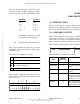

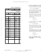
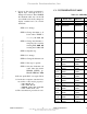
Table Of Contents
- COVER
- TABLE OF CONTENTS
- CHAPTER 1 GENERAL INFORMATION
- CHAPTER 2 DEBUG MONITOR DESCRIPTION
- CHAPTER 3 DEBUG MONITOR COMMANDS
- CHAPTER 4 ASSEMBLER/DISASSEMBLER
- CHAPTER 5 SYSTEM CALLS
- CHAPTER 6 DIAGNOSTIC FIRMWARE GUIDE
- APPENDIX A S-RECORD INFORMATION
- APPENDIX B SELF-TEST ERROR MESSAGES
- APPENDIX C USER CUSTOMIZATION
- LIST OF FIGURES
- LIST OF TABLES
- Table 2-1. Debugger Address Parameter Format
- Table 2-2. CPU32Bug Exception Vectors
- Table 3-1. Debug Monitor Commands
- Table 4-1. CPU32Bug Assembler Addressing Modes
- Table 5-1. CPU32Bug System Call Routines
- Table 6-1. MCU CPU Diagnostic Tests
- Table 6-2. Memory Diagnostic Tests
- Table B-1. Self-Test Error Messages
- Table C-1. CPU32Bug Customization Area
- Table C-2. MCU SCI Communication Formats
- Table C-3. Rev. A Chip Selection Summary
- Table C-4. Rev. B Chip Selection Summary
- Table C-5. BCC Rev. C Chip Selection Summary
- Table C-6. PFB Rev. C Compatibility
- CHAPTER 1 GENERAL INFORMATION
- CHAPTER 2 DEBUG MONITOR DESCRIPTION
- CHAPTER 3 DEBUG MONITOR COMMANDS
- 3.1 INTRODUCTION
- 3.2 BLOCK OF MEMORY COMPARE
- 3.3 BLOCK OF MEMORY FILL
- 3.4 BLOCK OF MEMORY MOVE
- 3.5 BREAKPOINT INSERT/DELETE
- 3.6 BLOCK OF MEMORY SEARCH
- 3.7 BLOCK OF MEMORY VERIFY
- 3.8 DATA CONVERSION
- 3.9 DUMP S-RECORDS
- 3.10 GO DIRECT (IGNORE BREAKPOINTS)
- 3.11 GO TO NEXT INSTRUCTION
- 3.12 GO EXECUTE USER PROGRAM
- 3.13 GO TO TEMPORARY BREAKPOINT
- 3.14 HELP
- 3.15 LOAD S-RECORDS FROM HOST
- 3.16 MACRO DEFINE/DISPLAY/DELETE
- 3.17 MACRO EDIT
- 3.18 MACRO EXPANSION LISTING ENABLE/DISABLE
- 3.19 MEMORY DISPLAY
- 3.20 MEMORY MODIFY
- 3.21 MEMORY SET
- 3.22 OFFSET REGISTERS DISPLAY/MODIFY
- 3.23 PRINTER ATTACH/DETACH
- 3.24 PORT FORMAT
- 3.25 REGISTER DISPLAY
- 3.26 COLD/WARM RESET
- 3.27 REGISTER MODIFY
- 3.28 REGISTER SET
- 3.29 SWITCH DIRECTORIES
- 3.30 TRACE
- 3.31 TRACE ON CHANGE OF CONTROL FLOW
- 3.32 TRANSPARENT MODE
- 3.33 TRACE TO TEMPORARY BREAKPOINT
- 3.34 VERIFY S-RECORDS AGAINST MEMORY
- CHAPTER 4 ASSEMBLER/DISASSEMBLER
- CHAPTER 5 SYSTEM CALLS
- 5.1 INTRODUCTION
- 5.2 SYSTEM CALL ROUTINES
- 5.2.1 Calculate BCD Equivalent Specified Binary Number
- 5.2.2 Parse Value, Assign to Variable
- 5.2.3 Check for Break
- 5.2.4 Timer Delay Function
- 5.2.5 Unsigned 32 x 32 Bit Divide
- 5.2.6 Erase Line
- 5.2.7 Input Character Routine
- 5.2.8 Input Line Routine
- 5.2.9 Input Serial Port Status
- 5.2.10 Unsigned 32 x 32 Bit Multiply
- 5.2.11 Output Character Routine
- 5.2.12 Output String Using Pointers
- 5.2.13 Print Carriage Return and Line Feed
- 5.2.14 Read Line to Fixed-Length Buffer
- 5.2.15 Read String Into Variable-Length Buffer
- 5.2.16 Return to CPU32Bug
- 5.2.17 Send Break
- 5.2.18 Compare Two Strings
- 5.2.19 Timer Initialization
- 5.2.20 Read Timer
- 5.2.21 Start Timer at T=0
- 5.2.22 Output String with Data
- 5.2.23 Output String Using Character Count
- CHAPTER 6 DIAGNOSTIC FIRMWARE GUIDE
- 6.1 INTRODUCTION
- 6.2 DIAGNOSTIC MONITOR
- 6.2.1 Monitor Start-Up
- 6.2.2 Command Entry and Directories
- 6.2.3 Help (HE)
- 6.2.4 Self Test (ST)
- 6.2.5 Switch Directories (SD)
- 6.2.6 Loop-On-Error Mode (LE)
- 6.2.7 Stop-On-Error Mode (SE)
- 6.2.8 Loop-Continue Mode (LC)
- 6.2.9 Non-Verbose Mode (NV)
- 6.2.10 Display Error Counters (DE)
- 6.2.11 Clear (Zero) Error Counters (ZE)
- 6.2.12 Display Pass Count (DP)
- 6.2.13 Zero Pass Count (ZP)
- 6.3 UTILITIES
- 6.4 CPU TESTS FOR THE MCU
- 6.5 MEMORY TESTS (MT)
- 6.6 BUS ERROR TEST
- APPENDIX A S-RECORD INFORMATION
- APPENDIX B SELF-TEST ERROR MESSAGES
- APPENDIX C USER CUSTOMIZATION

SELF-TEST ERROR MESSAGES
M68CPU32BUG REV 1 B-2
Table B-1. Self-Test Error Messages (continued)
Test Type and Error Message Failure Description
ROM Test:
ERROR $20 @ $000EXXXX, CONFIDENCE TEST FAILED Odd CODESIZE
ERROR $21 @ $000EXXXX, CONFIDENCE TEST FAILED Checksum error
RAM Test:
ERROR $30 @ $000EXXXX, CONFIDENCE TEST FAILED RAM error
CPU Addressing Test:
ERROR $40 @ $000EXXXX, CONFIDENCE TEST FAILED Absolute, immediate
ERROR $41 @ $000EXXXX, CONFIDENCE TEST FAILED Address indirect
ERROR $42 @ $000EXXXX, CONFIDENCE TEST FAILED Postincrement, pre-
decrement
ERROR $43 @ $000EXXXX, CONFIDENCE TEST FAILED Address indirect with
index
USER CUSTOMIZATION
M68CPU32BUG REV 1 C-1
APPENDIX C
USER CUSTOMIZATION
C.1 INTRODUCTION
Within the CPU32Bug certain operating parameters may be customized for the user’s particular
situation. This appendix details the customization features of CPU32Bug. An IBM-PC or
compatible host computer with the Motorola program BCC EPROM utility (PROGBCC) is
required to reprogram the EPROM on the BCC. This appendix assumes the user is using the
ProComm terminal emulation program on the host computer to communicate with CPU32Bug
and is familiar with the following; CPU32Bug, ProComm, MS-DOS, and PROGBCC.
NOTE
In the back of this appendix is a list of questions and answers. It
may be helpful to refer to the Q & A section before customizing
CPU32Bug.
CAUTION
Failure to incorporate changes as specified in this appendix may
cause malfunctions in the CPU32Bug. Novices should not attempt
to customize CPU32Bug.
The user customization area (parameter area) is the first 512 bytes of CPU32Bug ($E0000-
$E01FF), see Table C-1. For brevity’s sake, all entries have been shown as an offset value from
the $E0000 base address of CPU32Bug. The source code equivalent of the customization area,
initialization table, and chip select initialization module are available on the Motorola
FREEWARE Bulletin Board Service (BBS) under the archive filename C32SRC.ARC. Future
updates for CPU32Bug will also be available on the FREEWARE BBS under the archive
filename C32xxx.ARC. For more information on the FREEWARE BBS, reference customer
letter M68332EVS/L2.
Because there are two versions of the M68332BCC, there are two sets of chip select tables; one
set for Rev. A and one set for Rev. B. Upon power-up, CPU32Bug initializes the common
CSBOOT chip select and CS0/CS1 (see Rev. A table values). CPU32Bug then tests for RAM to
determine if the hardware is Rev. A or Rev. B. Chip select initialization then proceeds using the
values from the proper table. The only changes required by the user are to the WAIT CYCLES or
BASE ADDRESS fields for their platform board (PFB) sockets, or to use an unused chip select.
Fr
eescale S
emiconduct
or
, I
Freescale Semiconductor, Inc.
For More Information On This Product,
Go to: www.freescale.com
nc...