
Technical data


MOTOROLA MC68HC912B32
48 MC68HC912B32TS/D
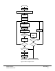
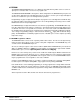
Figure 9 EEPROM Block Protect Mapping
8.2 EEPROM Control Registers
EESWAI — EEPROM Stops in Wait Mode
0 = Module is not affected during wait mode
1 = Module ceases to be clocked during wait mode
This bit should be cleared if the wait mode vectors are mapped in the EEPROM array.
PROTLCK — Block Protect Write Lock
0 = Block protect bits and bulk erase protection bit can be written
1 = Block protect bits are locked
Read anytime. Write once in normal modes (SMODN = 1), set and clear any time in special modes
(SMODN = 0).
EERC — EEPROM Charge Pump Clock
0 = System clock is used as clock source for the internal charge pump. Internal RC oscillator is
stopped.
1 = Internal RC oscillator drives the charge pump. The RC oscillator is required when the system
bus clock is lower than f
PROG
.
Read and write anytime.
Prevents accidental writes to EEPROM. Read anytime. Write anytime if EEPGM = 0 and PROTLCK = 0.
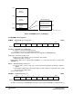
EEMCR — EEPROM Module Configuration $00F0
Bit 7 6 5 4 3 2 1 Bit 0
1 1 1 1 1 EESWAI PROTLCK EERC
RESET: 1 1 1 1 1 1 0 0
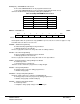
EEPROT — EEPROM Block Protect $00F1
Bit 7 6 5 4 3 2 1 Bit 0
1 1 1 BPROT4 BPROT3 BPROT2 BPROT1 BPROT0
RESET: 1 1 1 1 1 1 1 1
RESERVED (64 BYTES)
VECTORS (64 BYTES)
SINGLE CHIP VECTORS
HC912B32 EEPROM BLOCK PROT
$FF80
$FFBF
$FFC0
$FFFF
BPROT0
BPROT1
BPROT2
BPROT3
BPROT4
$_F00
$_E00
$_D00
$_F80
$_FC0
(256 BYTES)
(256 BYTES)
(128 BYTES)