
Technical data


MC68HC912B32 MOTOROLA
MC68HC912B32TS/D 73
12 Standard Timer Module
The standard timer module consists of a 16-bit software-programmable counter driven by a prescaler.
It contains eight complete 16-bit input capture/output compare channels and one 16-bit pulse accumu-
lator.
This timer can be used for many purposes, including input waveform measurements while simulta-
neously generating an output waveform. Pulse widths can vary from less than a microsecond to many
seconds. It can also generate PWM signals without CPU intervention.
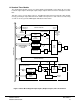
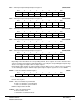
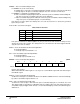
Figure 18 Timer Block Diagram: Input Capture, Output Compare, Pulse Accumulator
TFF
PAD
INT
OC7
PAD
INT
MUX
PAMOD
PULSE ACCUMULATOR
CONTROL REGISTERS
÷ 64
TC7
PIN
LOGIC
MODULE
CLOCK
16-BIT
COUNTER
BUFFER
LATCH
TC7
INPUT
PIN
POLARITY
CTL
GATE CLOCK
CTL
TIMPT
PIN
LOGIC
FUNCTION,
DIRECTION,
AND
POLARITY
CTL
CONTROL REGISTERS
PRESCALER
DIVIDE CTL
TCTL1 &
TCTL2
INPUT CAPTURE/
OUTPUT COMPARE
REGISTER
16-BIT
COMPARATOR
INTERMODULE BUS
OC
OUTPUT
IC
INPUT
BUFFER
LATCH - TIOC
TCRE
(COUNTER RESET)
TCNT
RESET
TCNT
16-BIT
COUNTER
PRESCALER
PR2, PR1, PR0
TIMER
COUNT
REGISTER
MODULE
CLOCK