
Operating instructions


Overview 2-7
MB*/* Installation and Operation Manual
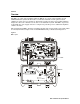
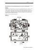
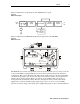
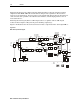
Figure 2-8 illustrates a block diagram of the MPPS-II power pack:
Figure 2-8
MPPS-II block diagram
EMI Filter
Overvoltage
and
power-factor
correction
60/90
Vac
24
Vdc
Preregulator
Isolation
transformer
Bridge
rectifier
Precision
regulator
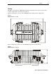
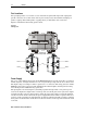
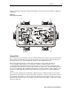
Figure 2-9 illustrates the MPPS-II installed in the upper half of the MB-HSG:
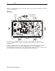
Figure 2-9
MPPS-II power pack
HI
LO
FTEC
AC TEST POINT
24V TEST POINT
MPPS-II
460132-001
NO US ER SERVIC ABL E
PARTS IN SIDE
USE CAUTION WHEN MAKING
INTERNAL ADJUSTMENTS
WITH COVER REMOVED
VOLTAGES IN EXCESS OF
300 VOLTS ARE PRESENT
UNDER COVER AND MAY
BE PRESEN T F OR SEVERAL
MINU TES AFTE R POW ER
IS REMOVED
SEE INSTALLATIO N MANUAL
FOR S ERVICE
The MPPS-II also contains a two position
LO/HI selector that sets the start-up voltage for 38 Vac
or 55 Vac. The MB*/* is shipped with the selector in the
LO position which is the standard
configuration. The selector should be switched to the
HI position only for a 90 Vac system. This
sets the start-up voltage at 55 Vac. Because this is only 5 V below 60 Vac, it is not practical to
switch to
HI in a 60 Vac system. There is no damage to the amplifier if the selector is not
changed from the standard
LO setting. However, changing the selector ensures that the dc
supply does not turn on until the proper input voltage, 38 Vac or 55 Vac, is reached. This
prevents excessive loading of the system power supply during turn-on after a system shutdown.