
Operating instructions


Overview 2-9
MB*/* Installation and Operation Manual
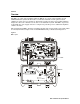
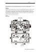
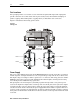
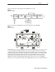
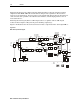
Factory installed 20-amp fuses, illustrated in Figure 2-11, provide power passing to additional
amplifiers:
Figure 2-11
Power passing fuse locations
RTN
EQ
MDR
MB 87 S G
J
A
K
E
M
75
55
-20dB
H
L
REFER TO
MANUAL FOR
FUSE VALUE S
IN
FUSE
PORT 3
POWER
CON TROL
STATUS
MONITOR
-20dB
JXP THERM
JXP
FUSE
JXP
IN
DRI VE
UNI T
MAN
3
4
BOD E
TDU
ADU
MAN
JXP 2
JXP 3/4
-16dB
STATUS
MONITOR
INPUT
A
DU
JXP
COMMON
H
L
-20dB
PORT 2
STATUS
MON ITOR
OUTPUT
-20dB
FUSE
JXP
ADU
JXP
HL
JXP 2
-20dB
I
C
S
I
C
S
-20dB
JXP 3/4
FUSE PORT 4
A
SSEMBLED IN MEXICO
CAUTION:
CONTAINS PARTS
AND ASSEMBLIES
SUSCEPTIBLE TO
DAMAGE BY
ELECTRO STAT IC
DISCHARGE (ESD)
FWD
EQ
ALIGN DOTS
F in
F3 location
F2
F4
Forward Path
The operational gain of all MB*/* models is 40 dB with 16 dB of return loss in the forward path.
The operating gain includes provisions for the insertion loss of the input cable equalizer and
required reserve gain to operate the Bode equalizer in the middle of its range.
The forward path’s electronics consist of two parallel three-stage paths consisting of:
(1) pre-amplifier (input hybrid), (2) intermediate amplifier (midstage hybrid), and
(3) power-doubling output hybrid stage. The first two stages are common to both paths. The
pre-amplifier stage provides a low noise figure while the output stage contributes the preferred
power at low distortion. The amplifier input provides a facility to install a cable equalizer and a
socket for a model JXP-*B attenuator. The attenuator and equalizer are customer installed
options.
Several circuits comprise the intermediate amplifier stages. A flatness control circuit enables
optimization of the frequency response. The Bode equalizer is a voltage-controlled device that, in
the standard configuration, receives its input from the manual gain control. It also receives its
input from the automatic drive unit (ADU-*) or thermal drive unit (TDU-*) when either of these
options is employed.