
Operating instructions


3-6 Amplifier Setup
MB*/* Installation and Operation Manual
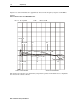
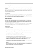
The information in Table 3-2 is shown as a graph in Figure 3-2:
Figure 3-2
Frequency versus cable slope
0
-1
-2
-3
-4
-5
-6
-7
-8
-9
-10
-11
-12
40
100
150
200
250
300
350
400
450
500
550
600
650
700
750
800
870
Cable slope (dB)
Frequency (MHz)
SCS-10
SCS-9
SCS-8
SCS-7
SCS-6
SCS-5
SCS-4
SCS-3
SCS-2
SCS-1
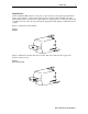
Input, Midstage, and Output Pads
Install model JXP-*B pads to attenuate the signal per system design drawings. Generally, this
consists of attenuating excessive input levels. You should pad the input to system level for unity
gain. Select and install the specified pad in the socket labeled
JXP-IN on the amplifier cover.
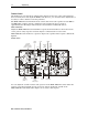
The midstage pad (JXP) and output pads (JXP2 and JXP3/4) can be used to adjust the gain level
and achieve the gain specification. Refer to Section 6, “Operating Tips” for midstage/output
padding information and recommendations.