
Operating instructions


3-8 Amplifier Setup
MB*/* Installation and Operation Manual
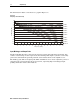
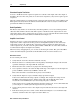
Flatness Control
All amplifiers are pre-aligned for optimal station flatness for the slope value ordered therefore,
there is usually no need to adjust the MDR board. However, you can make minor adjustments, if
necessary to achieve flatness across the passband.
The MDR-*MB/*/II board includes flatness controls and a fixed cable equalizer for 750 MHz or
870 MHz. This equalizer, plus the contribution of the hybrid gain stages, produces
approximately the dB of slope indicated by the model number (12 dB of tilt with an
MDR-*MB/12/II).
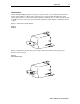
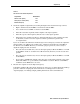
Adjust the MDR-*MB/*/II board and trimmer capacitors C116 and C118 on the main board to
correct peak-to-valley response variations. Figure 3-5 illustrates the location of the
MDR-*MB/*/II board and the two capacitors. Replace the equalizer if the response exhibits tilt.
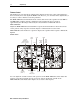
Figure 3-5
Flatness controls
A
uto
level (ADU)
ADU
or TDU
MD
R
Bode
board
C116
C118
Manual
level
(MAN)
ADU
pad
(JXP
ADU)
Forward
equalizer or
Cable simulator
(SFE-*-* or SCS-*)
SFE-*-*
DC/*
460246-001
Return
equalizer
(SRE-*-*)
DRIVE UNIT/MAN
Drive
control
select jumper
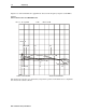
You can adjust the variable resistors and capacitors on the MDR-*MB/*/II board to flatten the
response across the passband. Use C1, C2, C3, C4, C6, C7, R2, R3, R4, and R5 on the
MDR-*MB/*/II board (illustrated in Figure 3-6) to obtain a flat response.