
Operating instructions


3-16 Amplifier Setup
MB*/* Installation and Operation Manual
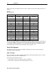
Table 3-4 provides the AGC pad values for other output levels. Recommended pad values are
shaded.
Table 3-4
MB*/* AGC pad levels
Amplifier ADU Control Range (dBmV)
MB*/* AGC Pad (10
to 14 dB tilt)
Minimum Level at
547.25 MHz
Midpoint Level at
547.25 MHz
Maximum Level at
547.25 MHz
6
35 39 43
7
36 40 44
8
37 41 45
9
38 42 46
10
39 43 47
11
40 44 48
12
41 45 49
14
42 46 50
15
43 47 51
16
44 48 52
17
45 49 53
18
46 50 54
19
47 51 55
20
48 52 56
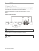
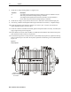
The use of the ADU or TDU is recommended for improved output level stability although you
can operate the MB*/* in the manual mode. Select manual mode by placing the drive control
select jumper, illustrated in Figure 3-5, in the
MAN position. The gain of the MB*/* is then
determined by the potentiometer marked
MAN on the amplifier cover.
Return Path Alignment
The following subsections describe the MB*/* alignment procedures required for proper
performance in the return path.
Before You Begin
Before you begin to set-up the amplifier and perform return-path alignment, please read the
following instructions and recommendations.
For proper return alignment obtain:
RF alignment levels and insertion points for all MB*/*s
RF reference output level of the headend optical receivers