
Operating instructions


Amplifier Setup 3-17
MB*/* Installation and Operation Manual
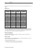
Equipment required for return-path alignment includes:
Full complement of JXP-*B pads and STARLINE Return Equalizers (SRE-*-*)
Reverse signal generator — must produce at least one signal within the return bandpass
and have variable output
Return sweep or alignment equipment
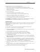
It is recommended that you:
Do not use wire jumpers to bypass the SRE-*-* location
Perform the return optical link set up before performing amplifier set up
Specify reverse alignment design levels for a single carrier
Consider sweep equipment as a single carrier and operate at design levels
Do not include injection point losses in reverse design levels
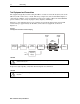
If JXP THERM devices (JXP-TH*B) are specified for level control, they should be installed in
the JXP THERM pad facility (illustrated in Figure 2-15) prior to alignment.
Alignment Procedure
The return amplifier configuration includes one low-gain (25 dB) or one high-gain (30 dB) return
amplifier hybrid, and an appropriate SRE-*-* equalizer. All components are plug-in and are
easily installed.
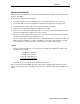
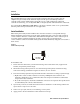
To align the return path:
1 If the MB*/* is powered, remove all fuses before you perform the following steps.
2 If necessary, carefully install a reverse hybrid amplifier.
3 Ensure that both hybrid screws are tight. Torque the screws to 10 to 12 in-lbs. Over-torque
can damage the hybrid.
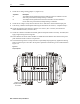
4 Install the design value pad in the return output pad location (JXP).
5 Install the design value return equalizer, SRE-*-*, in the location “RTN EQ”.
6 Verify that the return input pad locations (JXP 2 and JXP 3/4) have 0 dB pads
(or JXP-ZX jumpers) installed.
7 If the optional ICS is ordered, verify that the two switches (or one switch for single output
MB*/S*) are installed in the ICS locations. Otherwise, leave the factory-installed jumpers in
the two ICS locations.
8 Verify that the return pad (JXP COMMON) has a 0 dB pad (or JXP-ZX jumper) installed.
9 Verify that the return output pad socket (JXP THERM), located between the hybrid output
and the SRE-*-*, has a 0 dB pad (or JXP-ZX jumper) or a JXP-TH*B installed.
10 Set the sweep equipment output level to the amplifier’s design input level. Add insertion
point loss.
11 If required, change the return output pad (JXP) and/or return equalizer to achieve, as close
as possible, a match of the reference level as compared to the node.
12 Verify the sweep response of all insertion points, if applicable.