
Operating instructions


Bench Testing 4-5
MB*/* Installation and Operation Manual
4
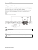
Measure the gain at the maximum return band frequency (example, 40 MHz for S-split).
The amplifier gain is the sum of: the measured gain, the insertion loss of the return cable
equalizer at the maximum return band frequency, the insertion loss of the power combiner,
any pads installed in either the input or output pad locations, plus the cable simulator loss
at the maximum return band frequency. The measured gain must meet advertised
specifications for the return amplifier.
Example
12.5 dB (measured gain)
+ 1.0 dB (equalizer insertion loss)
+ 0.6 dB (power combiner)
+ 0.0 dB (pads)
+ 4.6 dB (cable simulator at 40 MHz)
18.7 dB (unit gain)
Completing the Test Procedures
The amplifier is now approximately tailored for a specific field location. Additional adjustments
after installation are minor in nature. Re-install the fuses removed during testing.
Complete station records by recording pertinent information. Remove test-equipment
connections and close the housing following instructions provided in Section 5, “Installation,”
Closing the Housing.