
Operating instructions


5-2 Installation
MB*/* Installation and Operation Manual
7
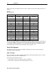
Check the ac voltage setting (jumper J1, Figure 2-10).
J1 position Description
LO
The voltage must be greater than 38 Vac as read with a true rms voltmeter or 42 Vac
when using a conventional, average reading, ac voltmeter.
HI
The voltage must be greater than 55 Vac when read with a true rms voltmeter or
61 Vac when using a conventional, average reading, ac voltmeter.
8
Check the dc voltage. Verify that it is between 23.6 V and 24.4 V and reinstall the input pad.
9 If necessary, rebalance the amplifier following the instructions in Section 3, “Amplifier Setup.”
10 Check the tightness of the electronic chassis cover screws (10 to 12 in-lbs.) and electronics
chassis hold-down bolts (18 to 22 in-lbs.).
11 Check the condition of the RF and weather gaskets and replace them if necessary. If needed, also
apply a light coating of silicone grease.
12 Ensure that the electronic chassis handles are folded down and that the cable between the power
pack and the electronics chassis is not pinched.
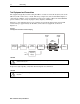
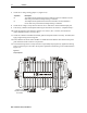
13 Close the housing and use a torque wrench to sequentially and progressively tighten the housing
bolts to a final torque of 12 ft-lb in the sequence specified on the housing cover and illustrated in
Figure 5-2.
Figure 5-2
Torque sequence
Torque in the
sequence shown
to 12 ft-lbs