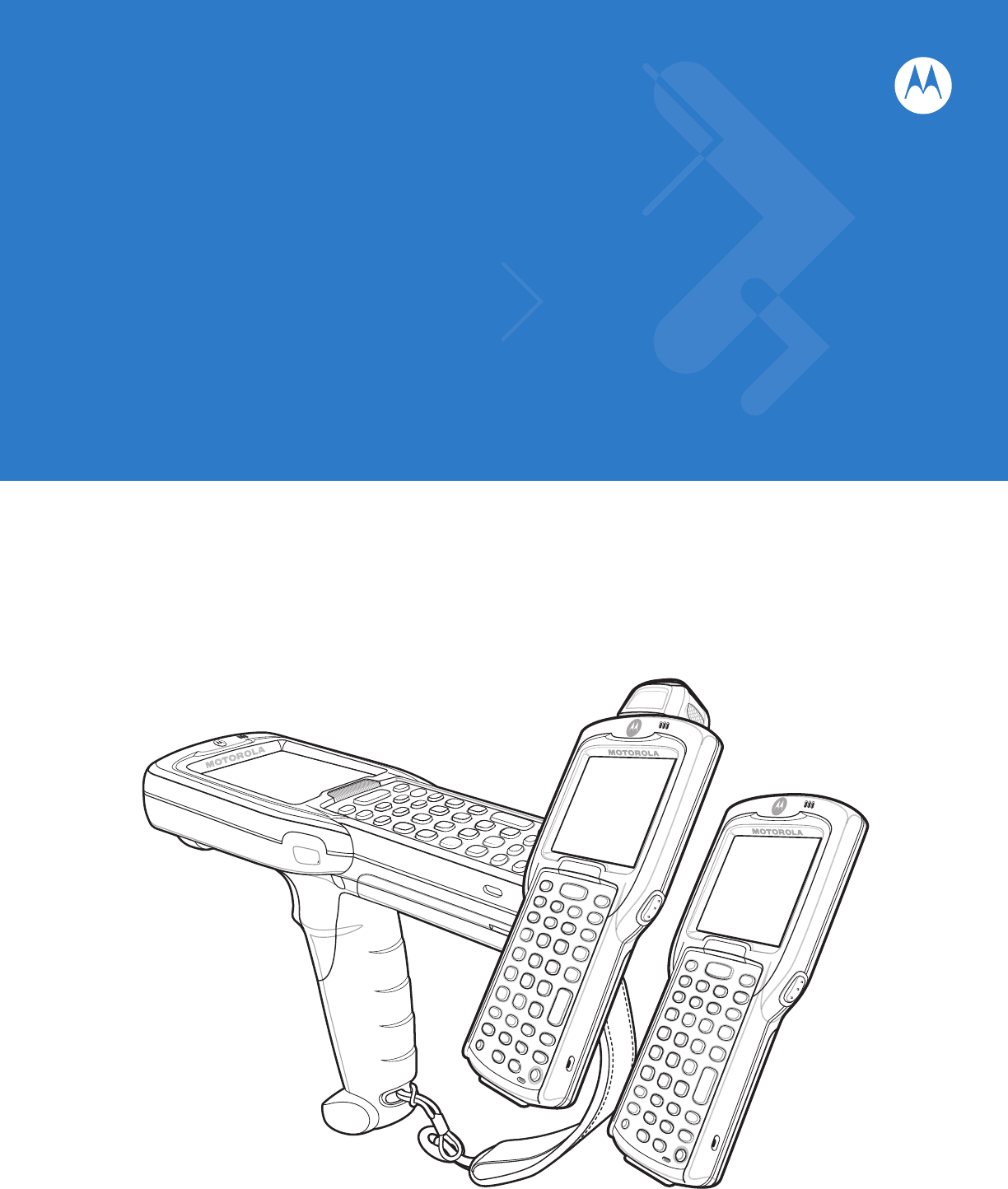
MC31XX Series Mobile Computer User Guide
MC31XX Series Mobile Computer User Guide 72E-124289-02 Revision A May 2010
ii MC31XX Series Mobile Computer User Guide © 2010 by Motorola, Inc. All rights reserved. No part of this publication may be reproduced or used in any form, or by any electrical or mechanical means, without permission in writing from Motorola. This includes electronic or mechanical means, such as photocopying, recording, or information storage and retrieval systems. The material in this manual is subject to change without notice. The software is provided strictly on an “as is” basis.
iii Revision History Changes to the original manual are listed below: Change Date Description -01 Rev A October 2009 Initial release. -02 Rev A May 2010 Add Windows Mobile 6.5.3 support with OEM version 02.27.
iv MC31XX Series Mobile Computer User Guide
Table of Contents Revision History .................................................................................................................................... iii About This Guide Introduction ........................................................................................................................................... Documentation Set ......................................................................................................................... Configurations...............
vi MC31XX Series Mobile Computer User Guide On Devices with Windows Mobile 6.X ........................................................................................... 1-17 Chapter 2: Operating the MC31XX Introduction .......................................................................................................................................... Power Button .......................................................................................................................................
Table of Contents vii Performing a Cold Boot ............................................................................................................ Windows Mobile 6.1 Devices ......................................................................................................... Performing a Warm Boot ......................................................................................................... Performing a Cold Boot .......................................................................
viii MC31XX Series Mobile Computer User Guide Bonding with Discovered Device(s) ............................................................................................... Bluetooth Settings .......................................................................................................................... Device Info Tab ........................................................................................................................ Services Tab ..........................................
Table of Contents Cleaning Cradle Connectors .......................................................................................................... Cleaning Frequency ....................................................................................................................... Troubleshooting ................................................................................................................................... Mobile Computer ........................................................
x MC31XX Series Mobile Computer User Guide
About This Guide Introduction This guide provides information about using the MC31XX mobile computers and accessories. NOTE Screens and windows pictured in this guide are samples and may differ from actual screens. For configurations with OEM version 02.27.000X and Windows Mobile 6.5 operating system, refer to Appendix C, Windows Mobile 6.5 for information about new features. Documentation Set The documentation set for the MC31XX is divided into guides that provide information for specific user needs.
xii MC31XX Series Mobile Computer User Guide Configurations This guide covers the following configurations: Configuration Radios Display Memory Data Capture Operating System Keypads MC3100R WPAN: Bluetooth Color 128 MB RAM/ 256 MB Flash or 256 MB RAM/512 MB Flash 1D laser scanner in rotating turret Windows CE 6.0 Professional 28, 38 or 48 key MC3100S WPAN: Bluetooth Color 128 MB RAM/ 256 MB Flash or 256 MB RAM/512 MB Flash 1D laser scanner, 2D imager Windows CE 6.
About This Guide The second line lists the operating system version and the build number. The last part of the build number represents the AKU number. For example, Build 20963.1.5.2 indicates that the device is running AKU version 1.5.2. OEM Version on Windows Mobile 6.X Devices To determine the OEM software version on a Windows Mobile 6.X device: Tap Start > Settings > System tab > System Information icon > System tab. OEM Version on Windows CE 6.
xiv MC31XX Series Mobile Computer User Guide Fusion Software To determine the Fusion software version on a Windows Mobile 6.X or Windows CE 6.0 device: Tap Wireless Strength icon > Wireless Status > Versions. Chapter Descriptions Topics covered in this guide are as follows: • Chapter 1, Getting Started, describes the mobile computer’s physical characteristics, how to install and charge the batteries, remove and replace the handstrap and how to start the mobile computer for the first time.
About This Guide Notational Conventions The following conventions are used in this document: • The term “mobile computer” refers to the Motorola MC31XX. • Italics are used to highlight the following: • Chapters and sections in this and related documents • Dialog box, window and screen names • Drop-down list and list box names • Check box and radio button names • Icons on a screen. • Bold text is used to highlight the following: • Key names on a keypad • Button names on a screen.
xvi MC31XX Series Mobile Computer User Guide Related Documents and Software The following items provide more information about the MC31XX mobile computers. • MC31XX Series Quick Start Guide, p/n 72-124259-xx • MC3190G Quick Start Guide, p/n 72-124276-xx • MC31XX Regulatory Guide, p/n 72-124293-xx • MC31XX Series Mobile Computer Integrator Guide, p/n 72E-68900-xx • Application Guide for Motorola Enterprise Mobility Devices, p/n 72E-68901-xx • Microsoft® Applications for Mobile 6.1 and CE 6.
Chapter 1 Getting Started Introduction This chapter describes the mobile computer physical characteristics, how to install and charge the batteries, how to remove and replace the handstrap and how to start the mobile computer for the first time. Unpacking the Mobile Computer Carefully remove all protective material from around the mobile computer and save the shipping container for later storage and shipping.
1-2 MC31XX Series Mobile Computer User Guide Scan LED Indicator (red/green) Rotating Scan Turret Scan LED Indicators (red/green) Beeper or Receiver (WLAN only) Display Indicator LED Bar Charge LED Indicator (amber) Scan Buttons Keypad Microphone (WLAN only) Power MC31XXR MC31XXS Figure 1-1 MC31XXS and MC31XXR Mobile Computers (Front View)
Getting Started Scan Window Headset Jack (WLAN only) Scan Window Speaker Headset Jack (WLAN only) Handstrap Screws Speaker Stylus Handstrap Stylus Holder Handstrap Latches MC31XXS MC31XXR Figure 1-2 MC31XXS and MC31XXR Mobile Computers (Back View) Rotating Scan Turret The MC31XXR mobile computer features a Rotating Scan Turret with three position stops. This feature offers greater scanning flexibility. CAUTION Do not try to rotate turret past side position stops. Damage to device can occur.
1-4 MC31XX Series Mobile Computer User Guide Scan LED Indicators (red/green) Charge LED Indicator (amber) Indicator LED Bar Display Scan Button Keypad Power Scan LED Indicator (red/green) Microphone Trigger Handstrap Figure 1-4 MC3190G Mobile Computer (Front View)
Getting Started 1-5 Stylus Silo Trigger Speakers Scan LED Indicator (red/green) Headset Jack Figure 1-5 MC3190G Mobile Computer (Back View) Mobile Computer Startup To start using the mobile computer: • Install the SD card. • Install the main battery. • Charge the main battery and the backup battery. • Start the mobile computer. Install SD Card The Secure Device (SD) card provides secondary non-volatile storage (the flash memory is slower than RAM). The SD card holder is located under the battery.
1-6 MC31XX Series Mobile Computer User Guide NOTE Select SD cards with environmental and/or the write cycle performance specifications that meet or exceed the application requirements. To insert the SD card: 1. Lift the SD card retaining door. 2. Position the SD card, with the contacts down, into the SD card slot. The SD card corner notch fits into the slot only one way. 3. Close SD card retaining door.
Getting Started Battery Figure 1-7 Insert Battery 3. With the latches in the open position, replace the battery door, top first and press to close. Door Latches Figure 1-8 Insert Battery Door 4. Rotate the latches (to the lock position) to lock the door in place.
1-8 MC31XX Series Mobile Computer User Guide Battery Charging CAUTION Ensure that you follow the guidelines for battery safety described in Battery Safety Guidelines on page 5-2. Use the mobile computer cradles, cables and spare battery chargers to charge the mobile computer main battery. The main battery can be charged before insertion into the mobile computer or after it is installed. There are two main batteries for the MC31XX, the Standard Battery (1X) and the Extended Life Battery (2X).
Getting Started 1-9 1. Insert the mobile computer into a cradle. See Chapter 4, Accessories for accessory setup. 2. The mobile computer starts to charge automatically. The amber Charge LED Indicator indicates the charge status. See Table 1-1 on page 1-9 for charging indications. To charge the mobile computer using the cables: 1. Connect the MC31XX Communication/Charge Cable to the appropriate power source and connect to the mobile computer. See Chapter 4, Accessories for accessory setup. 2.
1 - 10 MC31XX Series Mobile Computer User Guide To remove the stylus, slide the stylus out of the stylus holder. To store the stylus, push the stylus back into the stylus holder in the handstrap (MC31XXR/S) or stylus silo (MC3190G). Starting the Mobile Computer Press the Power button to turn on the mobile computer. If the mobile computer does not power on, perform a cold boot. See Resetting the Mobile Computer on page 2-23. When the mobile computer is powered on for the first time, it initializes.
Getting Started 1 - 11 Waking the Mobile Computer The wakeup condition settings are used to define what actions wake up the mobile computer. The settings are configurable so they are subject to change/update. For more information see, Waking the Mobile Computer on page 2-24. Main Battery Removal To remove the main battery from an MC31XXS/R: NOTE On devices with Windows Mobile 6.5.3, a dialog box appears when pressing the Power button. See Removing the Battery on page C-13 for more information. 1.
1 - 12 MC31XX Series Mobile Computer User Guide 6. With finger, press the battery clip in (at the top of the battery) and lift the battery out top first. WARNING! Do not use a tool to remove the battery. Battery Clip Figure 1-14 Remove Battery To remove the main battery from an MC3190G: NOTE On devices with Windows Mobile 6.5.3, a dialog box appears when pressing the Power button. See Removing the Battery on page C-13 for more information. 1.
Getting Started 1 - 13 Figure 1-16 Lift Door 6. With two finger, press the battery toward the bottom of the mobile computer and lift the battery out top first. WARNING! Do not use a tool to remove the battery. Figure 1-17 Press the Battery Toward Bottom of MC3190G Handstrap Removal and Replacement (MC31XXS/R) To remove the handstrap: 1. Use a #00 Phillips screwdriver to remove the screws. 2. Lift the mounting clip. 3. Slide the mounting clip out of the strap loop. 4.
1 - 14 MC31XX Series Mobile Computer User Guide #00 Phillips Screwdriver Strap Loop Mounting Clip Screws Mounting Clip Figure 1-18 Strap/Door Removal and Replacement (MC31XXS/R) To replace the handstrap: 1. Feed the mounting clip through the strap loop. 2. Secure the mounting clip to the housing using the two screws. 3. Feed the handstrap through the slot on the battery door. 4. Attach the hook material to the loop material and press together.
Getting Started 1 - 15 Figure 1-20 Remove Handstrap from Battery Door Slot To install a new handstrap: 1. Insert one end of the loop section into the mounting slot in the handle. 2. Thread the other end of the loop section through the loop and pull to tighten the loop. Figure 1-21 Thread Loop 3. Slip the button into the loop section. Button Loop Figure 1-22 Slip Button Through Loop 4. Thread the end of the handstrap into the slot in the battery door.
1 - 16 MC31XX Series Mobile Computer User Guide Figure 1-23 Thread Handstrap into Battery Door Slot 5. Press the hook material against the loop material.
Getting Started 1 - 17 Turning Off the Radios On Device with Windows CE 6.0 WLAN Radio To turn off the WLAN radio tap the Fusion Signal Strength icon on the task tray and select Disable Radio. A red X appears across the icon indicating that the radio is disabled (off). Fusion Signal Strength Icon Figure 1-24 Fusion Signal Strength Icon To turn the radio back on, tap the Fusion Signal Strength icon on the task tray and select Enable Radio.
1 - 18 MC31XX Series Mobile Computer User Guide Figure 1-27 Wireless Manager Window To enable or disable a wireless connection, tap its blue bar. To enable or disable all wireless connections, tap and hold the All bar. To configure settings for a connection, tap Menu.
Chapter 2 Operating the MC31XX Introduction This chapter provides basic instructions for using the mobile computer and navigating the mobile computer software. Power Button Press the red Power button to toggle the mobile computer between suspend and resume. When the screen is off the mobile computer is in suspend mode and when the screen is on the mobile computer is on. Windows CE Sample Applications Window The MC31XX with Windows CE contains a set of sample applications that can be installed.
2-2 MC31XX Series Mobile Computer User Guide Windows CE Desktop The desktop displays the applications available with the Windows CE configurations. For information on using the Microsoft® applications refer to the Microsoft® Applications for Mobile and CE 6.0 User Guide, p/n 72E-78456-xx. Figure 2-2 Windows CE Desktop Windows CE Status Icons The taskbar (at the bottom of the screen) displays the Start button, active programs, battery status and communication status.
Operating the MC31XX Open Programs and Status Icons Start Button Window Title Scroll Status Icons 2-3 Desktop Display Button Keyboard Input Panel Button Figure 2-3 Taskbar Table 2-1 Taskbar Icons Icon Description Indicates that the battery is charging. Indicates that the battery is fully charged (100% charged). The battery status icons provide the battery status in 10% increments from 10% to 100%. Indicates that communication with the smart battery has not been established.
2-4 MC31XX Series Mobile Computer User Guide Table 2-1 Taskbar Icons (Continued) Icon Description Indicates that the FUNC button function is selected. Indicates that the CTRL button function is selected. ALT Indicates that the ALT character selection is selected. Indicates that the mobile computer is in ALPHA button mode is selected. Battery Unknown Icon The Battery Unknown icon displays when communication with the smart battery has not been established.
Operating the MC31XX 2-5 Keyboard Input Panel Button Use the Keyboard Input Panel as an alternate input device. For more information, see Entering Information Using the Keyboard Input Panel on page 2-15. Desktop Display Button Use the Desktop Display button to minimize all open programs and display the desktop. • My Computer: Double-tap the icon to open My Computer. • Recycle Bin: Deleted files remain in the recycle bin until the recycle bin is emptied. Once emptied the files cannot be retrieved.
2-6 MC31XX Series Mobile Computer User Guide • Check the AutoHide checkbox to make the taskbar disappear, touch the bottom of the display to make the taskbar return. • Check the Show Clock checkbox to display the clock on the taskbar. 4. Tap OK to save the settings and exit the window. Figure 2-5 Taskbar and Start Menu, General Tab Advanced Tab 1. Tap the Advanced tab to enter the Taskbar and Start Menu, Advanced tab. 2.
Operating the MC31XX 2-7 Connectivity Notification Open the Start Menu Adjust volume Battery Status Change the date and time Turn on or off radios Fusion Signal Strength IST Command Bar Soft Keys Figure 2-7 Today Screen To customize the Today screen, tap Start > Settings > Today icon. Use the Appearance tab to customize the background and the Items tab to change the list and order of items that appear on the screen. Windows Mobile 6.1 Status Icons Status Bar NOTE On devices with Windows Mobile 6.
2-8 MC31XX Series Mobile Computer User Guide Table 2-2 Status Icons (Continued) Icon Function Connectivity Description Connection is active. ActiveSync error Synchronization is occurring. Instant Message Notification that one or more instant messages were received. E-Mail Notification that one or more e-mail messages were received. Time and Next Appointment Displays current time in analog or digital format. Multiple Notifications There are more notification icons than can be displayed.
Operating the MC31XX 2-9 Table 2-3 Command Bar Icons (Continued) Icon Description The Bluetooth Communication icon appears in the task tray and indicates that the mobile computer is communicating with another Bluetooth device (Displays only if the StoneStreet One Bluetooth stack is enabled). Opens the IST control panel. The ActiveSync icon appears in the task tray and indicates an active serial connection between the mobile computer and the development computer.
2 - 10 MC31XX Series Mobile Computer User Guide Figure 2-10 Battery Icon on the Title Bar You can also view the battery status using the Power window. When the main battery power falls below a predetermined level a Main Battery dialog box appears indicating the status of the main battery. When the backup battery power falls below a predetermined level a Backup Battery icon and dialog box appears indicating the status of the backup battery.
Operating the MC31XX 2 - 11 Digital Clock Analog Clock Figure 2-13 Time Icon Format Menu To display current date, time and appointments: 1. Tap the Time icon to display the Time and Next Appointment dialog box. Battery Status Icon Upcoming Appointments Current Date and Time Figure 2-14 Time and Next Appointment Dialog Box 2. The dialog box displays the current date and time, the battery status and any upcoming appointments in the Calendar.
2 - 12 MC31XX Series Mobile Computer User Guide Figure 2-16 Multiple Notifications Icon Locking the Mobile Computer (Windows Mobile 6.1 Only) NOTE On devices with Windows Mobile 6.5.3, the locking feature is different. See Locking the MC3100 on page C-10 for more information. You can lock the MC311XX by disabling key presses and screen tap or by requiring a password. Keypad Locking Locking the MC31XX turns off keyboard and touch screen functionality.
Operating the MC31XX 2 - 13 Password Locking Use the Password window to set a password to disable unauthorized access to the MC31XX. NOTE 1. If the device is configured to connect to a network, use a strong (difficult to figure out) password to help protect network security. Password cracking tools continue to improve and the computers used to crack passwords are more powerful than ever. Tap Start > Settings > Personal tab > Lock icon > Password tab. Figure 2-19 Password Window - Password Tab 2.
2 - 14 MC31XX Series Mobile Computer User Guide When the MC31XX is not used for a period of time and the user tries to access the device, the Password window appears. Figure 2-21 Enter Password Windows Enter the password to un-lock the device. Tap Unlock.
Operating the MC31XX 2 - 15 Entering Information To enter information: • Use the keypad. • Use the keyboard input panel (soft keyboard) to enter text. • Scan bar code data into data fields. • Use Microsoft® ActiveSync® to synchronize or copy information from the host computer to the mobile computer. For more information on ActiveSync, refer to the MC31XX Series Mobile Computer Integrator Guide.
2 - 16 MC31XX Series Mobile Computer User Guide Interactive Sensor Technology This section describes the functionality of the Interactive Sensor Technology (IST) feature on the MC31XX. The IST supports the following features. • Power Management – manage power by configuring IST to control switching on/off the backlight, control suspend mode of the MC31XX by monitoring motion and orientation.
Operating the MC31XX 2 - 17 Free Fall Detection IST continuously monitors gravitational force on the MC31XX according to its current position. When the MC31XX free falls, IST detects the absence of gravitational force and records the event data if it detects a free fall more than 450 ms, which may indicate nearly a one meter drop. This data can be used as an indicator of potential abuse or misuse. IST features a log for recording the free fall events.
2 - 18 MC31XX Series Mobile Computer User Guide Connecting a Wired headset To connect a wired headset to the MC31XX: Figure 2-25 Connect Headset to MC31XX
Operating the MC31XX 2 - 19 Using a Bluetooth Headset You can use a Bluetooth headset for audio communication when an audio enabled application is used. See Chapter 3, Using Bluetooth for information on connecting a Bluetooth device to the mobile computer. Ensure that the mobile computer’s volume is set appropriately before putting the headset on. When a Bluetooth headset is connected the speaker is muted.
2 - 20 MC31XX Series Mobile Computer User Guide Table 2-4 Scan LED Indicators LED Status Indication Off Not scanning. Solid Red Laser enabled, scanning in process. Solid Green Successful decode. Scanning Considerations Scanning consists of; aim, scan and decode. Scanning performance can be optimized by considering the range and the scanning angle: • Range Any scanning device decodes well over a particular working range (minimum and maximum distances from the bar code).
Operating the MC31XX 2 - 21 Operational Modes MC31XX with an integrated imager support three modes of operation, listed below. Activate each mode pressing the Scan button. • Decode Mode: In this mode, the MC31XX attempts to locate and decode enabled bar codes within its field of view. The imager remains in this mode as long as you hold the scan button, or until it decodes a bar code. NOTE To enable Pick List Mode, download the Control Panel applet from the Support Central web site at http://www.motorola.
2 - 22 MC31XX Series Mobile Computer User Guide Figure 2-28 Pick List Mode with Multiple Bar Codes 4. Release the scan button. NOTE Imager decoding usually occurs instantaneously. The MC31XX repeats the steps required to take a digital picture (image) of a poor or difficult bar code as long as the scan button remains pressed.
Operating the MC31XX 2 - 23 Resetting the Mobile Computer Windows CE 6.0 Devices If the mobile computer stops responding to input, reset it. There are two reset functions, warm boot and cold boot. A warm boot restarts the mobile computer by closing all running programs. All data that is not saved is lost. A cold boot also restarts the mobile computer, but erases all stored records and entries from RAM. In addition it returns formats, preferences and other settings to the factory default settings.
2 - 24 MC31XX Series Mobile Computer User Guide 2. As the mobile computer initializes Today screen appears. Performing a Cold Boot A cold boot restarts the mobile computer. The operating system and all applications are restarted. File storage is preserved and some drivers are initialized. Only perform a cold boot if a warm boot does not solve the problem. 1. To perform a cold boot, simultaneously press and then release the 1, 9 and Power keys. Do not hold down any other keys or buttons. 2.
Operating the MC31XX 2 - 25 Figure 2-29 Windows CE 6.0 Wakeup Tab On Windows Mobile 6.1 devices, tap Start > Settings > System tab > Power icon > Wakeup tab. Figure 2-30 Windows Mobile 6.
2 - 26 MC31XX Series Mobile Computer User Guide
Chapter 3 Using Bluetooth Introduction Bluetooth-equipped devices can communicate without wires, using frequency-hopping spread spectrum (FHSS) radio frequency (RF) to transmit and receive data in the 2.4 GHz Industry Scientific and Medical (ISM) band (802.15.1). Bluetooth wireless technology is specifically designed for short-range (30 feet/10 meters) communication and low power consumption. MC31XXs with Bluetooth capabilities can exchange information (e.g.
3-2 MC31XX Series Mobile Computer User Guide NOTE It is not recommended to perform Bluetooth wireless technology inquiry when high rate 802.11b operation is required. Security The current Bluetooth specification defines security at the link level. Application-level security is not specified. This allows application developers to define security mechanisms tailored to their specific need.
Using Bluetooth 3-3 Table 3-1 Bluetooth Services Microsoft Bluetooth Stack Windows Mobile Serial Port Service WinCE Serial Port Service StoneStreet One Bluetooth Stack Windows Mobile WinCE Serial Port Service Serial Port Service Dial-Up Networking Client Service Dial-Up Networking Client Service Dial-Up Networking Client Service OBEX Object Push Service OBEX Object Push Client and Host Services OBEX Object Push Client and Host Services HID Client Service HID Client Services HID Client Servi
3-4 MC31XX Series Mobile Computer User Guide With Microsoft Bluetooth Stack Performing a cold boot retain the state of the Bluetooth radio prior to the cold boot. Warm Boot With StoneStreet One Bluetooth Stack Performing a warm boot turns off Bluetooth. With Microsoft Bluetooth Stack Performing a warm boot retain the state of the Bluetooth radio prior to the warm boot. Suspend When there is an active Bluetooth connection, the Bluetooth radio goes into low power mode maintaining the active connection.
Using Bluetooth 3-5 Using Microsoft Bluetooth Stack with Windows Mobile 6.1 The following sections provide information on using the Microsoft Bluetooth stack with the Windows Mobile 6.1 operating system. Turning the Bluetooth Radio Mode On and Off Turn off the Bluetooth radio to save power or if entering an area with radio restrictions (e.g., an airplane). When the radio is off, other Bluetooth devices cannot see or connect to the MC31XX.
3-6 MC31XX Series Mobile Computer User Guide Discovering Bluetooth Device(s) The MC31XX can receive information from discovered devices without bonding. However, once bonded, the MC31XX and a bonded device exchange information automatically when you turn the Bluetooth radio on. See Bonding with Discovered Device(s) on page 3-30 for more information. To find Bluetooth devices in the area: 1. Ensure that Bluetooth is enabled on both devices. 2.
Using Bluetooth 3-7 Figure 3-5 Enter Passcode 8. Enter the Passcode on the other device. The device is added to the Bluetooth list. Figure 3-6 Bluetooth Connection Confirmation You are prompted to enter a passcode. If the device has a specific passcode, enter it in the Passcode field and tap Next. If the device does not have a specific passcode, enter one in the Passcode field and tap Next. The Bluetooth radio tries to connect with the device. 9.
3-8 MC31XX Series Mobile Computer User Guide • HID • Dial-up Networking • A2DP/AVRCP. See the following sections for information on these services. Object Push Services via Beam NOTE You can only send files to a remote device using the Beam function. Use the OBEX Push Service to send files and contacts to another Bluetooth device. To transfer files between the MC31XX and another Bluetooth enabled device: 1. Ensure that Bluetooth is enabled and discoverable on both devices. 2.
Using Bluetooth 1. Ensure that Bluetooth is enabled and discoverable on both devices. 2. Ensure that the two devices are within 30 feet (10 meters) of one another. 3. Tap Start > Contacts 4. Navigate to the contact to transfer. 5. Tap and hold on the contact until the pop-up menu appears. 3-9 Figure 3-9 Contact Window 6. Select Send Contact > Beam. The MC31XX searches for Bluetooth devices in the area. 7. Tap Tap to send next to the Bluetooth device to send the file to.
3 - 10 MC31XX Series Mobile Computer User Guide 13. Select the serial device in the list and then tap Next. 14. Select a COM port from the drop-down list. 15. Tap Finish. NOTE No connection is made at this point. An application must open the selected COM port to trigger Microsoft Bluetooth stack to open the connection. ActiveSync Using Serial Port Services Use the wireless Bluetooth serial port connection for ActiveSync just as you would a physical serial cable connection.
Using Bluetooth 3 - 11 6. On the COM Ports tab, click Add. 7. Select the Incoming (device initiates the connection) option, then click OK. Note the number of the COM port that was added. 8. Click OK. 9. Click Start > All Programs > Microsoft ActiveSync. 10. Click File > Connection Settings. Figure 3-11 ActiveSync Connection Settings 11. On the Allow connections to one of the following drop-down list, select the COM port with the number you noted earlier. 12.
3 - 12 MC31XX Series Mobile Computer User Guide Using Microsoft Bluetooth Stack with Windows CE 6.0 The following sections provide information on using the Microsoft Bluetooth stack with Windows CE 6.0 operating system. Power Modes The Bluetooth radio switches between normal and low power modes automatically. When data transfer is required, the radio goes into normal mode. After five seconds of inactivity, the radio goes into low power mode.
Using Bluetooth 3 - 13 8. Tap Yes. 9. The Bluetooth Enter PIN window appears. Figure 3-14 Enter PIN 10. Enter the PIN on the other device. The device is added to the Trusted list. You are prompted to enter a PIN. If the device has a specific PIN, enter it in the PIN field and tap Next. If the device does not have a specific passcode, enter one in the Passcode field and tap Next. The Bluetooth radio tries to connect with the device. 11.
3 - 14 MC31XX Series Mobile Computer User Guide Using Bluetooth StoneStreet One Bluetooth Stack The following sections provide information on using the Stone Street One Bluetooth stack. Turning the Bluetooth Radio Mode On and Off Turn off the Bluetooth radio to save power or if entering an area with radio restrictions (e.g., an airplane). When the radio is off, other Bluetooth devices cannot see or connect to the MC31XX.
Using Bluetooth 3 - 15 NOTE Switching between Wizard Mode and Explorer Mode closes all active connections. Wizard Mode shows the devices and services in a simple Favorites view created by following the step-by-step wizard. Explorer Mode The Explorer Mode window is easy to navigate and provides greater control to users familiar with Bluetooth. The menu bar provides quick access to the options and tools used to connect to devices. To access Explorer Mode, tap View > Explorer Mode.
3 - 16 MC31XX Series Mobile Computer User Guide NOTE 6. If favorite connections have already been created, the Favorites screen displays. If no favorite connections have been created, the New Connection Wizard screen displays. Tap Menu > New Connection.The New Connection Wizard appears. Figure 3-18 BTExplorer Window 7. Select Explore Services on Remote Device or another from the drop-down list and tap Next.
Using Bluetooth 3 - 17 Figure 3-19 Discover Devices Dialog Box The discovered devices display in the Select Remote Device window. Figure 3-20 Select Remote Device Window 9. Select a device from the list and tap Next. The MC31XX searches for services on the selected Bluetooth device. Figure 3-21 Device Services NOTE If the MC31XX discovers a service but the service is not supported, the service icon is grayed-out. 10. Select a service from the list and press Next.
3 - 18 MC31XX Series Mobile Computer User Guide Figure 3-22 Connection Favorite Options Window 11. In the Favorite Name text box, enter a name for this service that will appear in the Favorite window. 12. Tap Next. The Connection Summary window appears. 13. Tap Connect to add the service to the Favorite window and connect to the service. Figure 3-23 Favorites Window Available Services NOTE Some devices might not require a PIN. This depends upon the device’s authentication.
Using Bluetooth 3 - 19 File Transfer Services NOTE Shared folders are a security risk. To transfer files between the MC31XX and another Bluetooth enabled device: 1. Ensure that OBEX File Transfer profile is enabled on the MC31XX. See Profiles Tab on page 3-42 for more information. NOTE If favorite connections have already been created, the Favorites screen displays. If no favorite connections have been created, the New Connection Wizard screen displays. 2.
3 - 20 MC31XX Series Mobile Computer User Guide • Get File - copy the file from the remote device to the MC31XX. • Put File - copy a file from the MC31XX to the remote device. Creating a New File or Folder To create a new folder or file on the remote device: 1. Tap and hold on the screen and select New > Folder or New > File. The Create New Folder or Create New File window appears. 2. Enter the name for the new folder or file. 3. Tap OK to create the new folder or file on the remote device.
Using Bluetooth 3 - 21 5. Tap Start > Internet Explorer. The Internet Explorer window appears. 6. In the address field, enter an internet address and tap the Enter button. The web page loads. NOTE Network Access profile is not supported. Dial-Up Networking Services Dial-up networking allows the user to connect the MC31XX to a Bluetooth Phone and use the Bluetooth Phone as a modem to connect to an office network or ISP.
3 - 22 MC31XX Series Mobile Computer User Guide Figure 3-27 Connection Favorite Options Window 8. In the Favorite Name text box, enter a name for this service that will appear in the Favorite window. 9. Tap Next. The Connection Summary window appears. 10. Tap Connect. The Select Dial-up Networking Entry window appears. Figure 3-28 Select Dial-up Networking Entry Window 11. Select the entry and tap OK. The MC31XX begins to communicate with the Bluetooth phone.
Using Bluetooth 3 - 23 18. To end a session, tap the Connection icon and then tap Disconnect in the dialog box. Add a Dial-up Entry To add a dial-up entry: 1. In the Select Dial-up Networking Entry window, tap and hold and then select Add Entry from the pop-up menu. Figure 3-30 Select Dial-up Networking Entry Window 2. The Add Phone Book Entry window appears. Figure 3-31 Add Phone Book Entry Window 3. In the Name for the connection text box, enter a name for this connection. 4.
3 - 24 MC31XX Series Mobile Computer User Guide NOTE If favorite connections have already been created, the Favorites screen displays. If no favorite connections have been created, the New Connection Wizard screen displays. 3. Use the Connection Wizard to search for a Bluetooth device. 4. Select the device and tap Next. 5. Select the OBEX Object Push service and select Next. The Connection Favorite Options window appears. 6. Tap Next. The Connection Summary window appears. 7. Tap Connect.
Using Bluetooth 3 - 25 5. Tap OK. 6. Tap OK to send the contact to the other device and display a confirmation dialog box on the other device to accept the contact. A Send Contact dialog appears. 7. Tap Ok. Swapping Contacts To swap contacts with another device: NOTE Prior to swapping contacts, a default contact must be set up before attempting to send a contact. Ensure that the MC31XX is connectable. 1. Tap and hold on OBEX Object Push and select Connect. The OBEX Object Push window appears.
3 - 26 MC31XX Series Mobile Computer User Guide Fetching a Contact To fetch a contact from another device: NOTE Prior to sending and receiving contacts, a default contact must be set up before attempting to send a contact. Ensure that the MC31XX is connectable. 1. Tap and hold on OBEX Object Push and select Connect. The OBEX Object Push window appears. Figure 3-36 OBEX Object Push Window 2. In the Action: drop-down list, select Fetch Contact information. 3. Tap OK.
Using Bluetooth 3 - 27 Figure 3-38 Send Local Picture Window 4. Navigate to the picture to send to the other device. 5. Tap Open. 6. Tap OK to send the picture to the other device and display a confirmation dialog box on the other device to accept the picture. A Send Picture dialog appears. 7. Tap Ok. Headset Services To connect to a Bluetooth headset: NOTE Newer Bluetooth headsets are device dependant and remember the last device they connected to.
3 - 28 MC31XX Series Mobile Computer User Guide To establish a serial port connection: 1. MC31XXUse the Connection Wizard to search for a Bluetooth serial device. 2. Select the device and tap Next. The Connection Favorite Options window appears. 3. In the Local COM Port: drop-down list select a COM port. 4. Tap Finish. ActiveSync Using Serial Port Services NOTE By default, COM ports COM5, COM9, COM11, COM21, COM22 and COM23 are Bluetooth virtual ports.
Using Bluetooth 3 - 29 5. In the Service Type drop-down list, select Active Sync. 6. Tap OK. The MC31XX connects the PC and an ActiveSync session begins. 7. Tap Finish. The Connection Favorite Options window appears. 8. To end the session, tap the ActiveSync icon in the Favorite window and select Disconnect from the pop-up window. Personal Area Network Services NOTE This profile supports Ad-hoc and PAN User. Network Access Profile is not supported.
3 - 30 MC31XX Series Mobile Computer User Guide 14. Tap Next. 15. Tap Connect. The MC31XX connects to the high-quality audio headset. For stereo headsets that can use hands-free services, connect to the hands-free service after connecting to the A2DP service: 1. Tap Menu > New Connection. 2. Select Connect to Headset from the drop-down list. 3. Tap Next. 4. Select the stereo headset and tap Next. 5. Select the Hands-Free unit service and then tap Next. 6. Tap Next. 7. Tap Connect.
Using Bluetooth 3 - 31 1. Tap the Bluetooth icon and select Show BTExplorer. The BTExplorer window appears. 2. Tap Menu > New Connection. The New Connection Wizard window appears. 3. In the drop-down list, select Pair with Remote Device. 4. Tap Next. The Select Remote Device window appears. NOTE Devices discovered previously are listed to save time. To start a new device discovery, tap and hold on the list area and select Discover Devices from the pop-up menu.
3 - 32 MC31XX Series Mobile Computer User Guide Figure 3-43 Pairing Status Window 8. Tap Finish. The devices are successfully paired. The device name moves to the Trusted Devices window. Deleting a Bonded Device To delete a device no longer needed: 1. Tap the Bluetooth icon and select Show BTExplorer. The BTExplorer window appears. 2. Tap Menu > Trusted Devices. The Trusted Devices window appears. 3. Tap and hold on the device select Delete Link Key in the pop-up menu. 4.
Using Bluetooth 3 - 33 4. Tap OK to create the bond. The MC31XX can now exchange information with the other device. Bluetooth Settings Use the BTExplorer Settings window to configure the operation of the BTExplorer application. Tap Menu > Settings. The BTExplorer Settings window appears. Device Info Tab Use the Device Info tab to configure the MC31XX’s Bluetooth connection modes.
3 - 34 MC31XX Series Mobile Computer User Guide 1. Tap Add. The Add Local Service window displays. Figure 3-47 Add Local Service Window 2. In the list, select a service to add. 3. Tap OK. The Edit Local Service window displays for the selected service. 4. Select the appropriate information and then tap OK. See the following sections for information on the available services. Dial-Up Networking Service Dial-up Networking allows other Bluetooth devices to access a dial-up modem.
Using Bluetooth 3 - 35 Table 3-4 Dial-up Networking Information Data Item Description Local COM Port Select the COM port. Local Baud Rate Select the communication baud rate. Local Port Options Select the port option. File Transfer Service File transfer allows other Bluetooth devices to browse files. Figure 3-49 BTExplorer Settings - File Transfer Information Table 3-5 File Transfer Information Data Item Description Service Name Displays the name of the service.
3 - 36 MC31XX Series Mobile Computer User Guide Headset Audio Gateway Service Headset Service Audio Gateway allows connection to headset devices. Figure 3-50 BTExplorer Settings - Headset Audio Gateway Table 3-6 Headset Audio Gateway Data Item Description Service Name Lists the name of the audio service. OBEX Object Push Service OBEX Object Push allows other Bluetooth devices to push contacts, business cards, pictures, appointments, and tasks to the MC31XX.
Using Bluetooth 3 - 37 Table 3-7 OBEX Exchange Information Data Item Description Service Security Select the type of security from the drop-down list. Options are None, Authenticate, or Authenticate/Encrypt. Do not allow clients to push objects Disables clients from pushing objects to the MC31XX. Inbox Directory Select a directory where another Bluetooth device can store files.
3 - 38 MC31XX Series Mobile Computer User Guide Figure 3-53 BTExplorer Settings - Serial Port Services Table 3-9 Serial Port Services Data Item Description Service Name Displays the name of the service. Service Security Select the type of security from the drop-down list. Options are None, Authenticate, or Authenticate/Encrypt. Local COM Port Select the COM port. Local Baud Rate Select the communication baud rate. Local Port Options Select the port option.
Using Bluetooth 3 - 39 Audio Video Remote Control Service Audio Video Remote Control hosts connections from Bluetooth devices supporting audio remote-control functionality. Figure 3-55 BTExplorer Settings - Audio Video Remote Control Table 3-11 Audio Video Remote Control Data Item Service Name Description Lists the name of the audio service. Security Tab Security settings allows you to set global security policies for Bluetooth.
3 - 40 MC31XX Series Mobile Computer User Guide Table 3-12 Security Tab Data Item Description Use PIN Code (Incoming Connection) Select for automatic use of the PIN code entered in the PIN Code text box. It is recommended not to use this automatic PIN code feature. See Security on page 3-2 for more information. PIN Code Enter the PIN code. Encrypt Link On All Outgoing Connections Select to enable or disable encryption on all outgoing connections to other Bluetooth devices.
Using Bluetooth 3 - 41 Figure 3-58 BTExplorer Settings - Virtual COM Port Tab Table 3-14 Virtual COM Port Tab Data Item Description COM5:Bluetooth Enable or disable COM Port 5. COM9:Bluetooth Enable or disable COM Port 9. COM11:Bluetooth Enable or disable COM Port 11. COM21:Bluetooth Enable or disable COM Port 21. COM22:Bluetooth Enable or disable COM Port 22. COM23:Bluetooth Enable or disable COM Port 23.
3 - 42 MC31XX Series Mobile Computer User Guide Figure 3-59 BTExplorer Settings - HID Tab Table 3-15 HID Tab Data Item Description Enable Key Repeat Enables key repeat functionality. Delay To increase key repeat delay, drag the Delay slider to the right. To decrease key repeat delay, drag the Delay slider to the left. Rate To increase key repeat speed, drag the Rate slider to the left. To decrease key repeat speed, drag the Rate slider to the right.
Using Bluetooth 3 - 43 System Parameters Tab Figure 3-61 BTExplorer Settings - System Parameters Tab Table 3-16 System Parameters Tab Data item Description Page Timeout Sets the amount of time the MC31XX searches for a device before moving on the next device. Link Supervision Timeout Sets the amount of time that the MC31XX will wait for a device to come back into range after it has gone out of range. If the device does not come back into range by the set time, the MC31XX drops the connection.
3 - 44 MC31XX Series Mobile Computer User Guide
Chapter 4 Accessories Introduction The MC31XX accessories provide a variety of product support capabilities. Accessories include cradles, cables and spare battery chargers. Table 4-1 lists the MC31XX accessories. Table 4-1 MC31XX Accessories Accessory Part Number Description Cradles Single Slot Serial/USB Cradle CRD3000-1001RR Charges the mobile computer main battery and a spare battery, and synchronizes the mobile computer with a host computer through either a serial or USB connection.
4-2 MC31XX Series Mobile Computer User Guide Table 4-1 MC31XX Accessories (Continued) Accessory Part Number Description Power Supply for Single Slot Serial/USB Cradle KT-14000-148R Provides power to the Single Slot Serial/USB Cradle and Four Slot Battery Charger. Power Supply for Four Slot Cradles 50-14000-241R Provides power to the Four Slot Charge Only and Ethernet Cradles. Power Supply for Charging Cables 50-14000-249R Provides power to the charge only, serial cable and USB cable.
Accessories 4-3 Table 4-1 MC31XX Accessories (Continued) Accessory Part Number Description Headset Adapter Cable: MC3100 2.5 mm jack with unique locking screw to bare wires 25-124389-01R Connects a headset with unique Quick Disconnect Connector to the mobile computer. Bare wires can be soldered to user defined unique Quick Disconnect Connector. Headset Adapter cable: MC3100 2.
4-4 MC31XX Series Mobile Computer User Guide Table 4-1 MC31XX Accessories (Continued) Accessory Part Number Description MC31XXR/S Handstrap SG-MC3123243-01R Replacement handstrap for MC31XXR and MC31XXS. MC31XX 1X Battery Door KT-128372-01R Replacement 1X battery door for MC31XXR and MC31XXS. MC31XX 2X Battery Door KT-128373-01R Replacement 2X battery door for MC31XXR and MC31XXS. MC3190G 2X Battery Door KT-128374-01R Replacement 2X battery door for MC3190G.
Accessories 4-5 Single Slot Serial/USB Cradle CAUTION Ensure that you follow the guidelines for battery safety described in Battery Safety Guidelines on page 5-2. The Single Slot Serial/USB cradle: • Provides 5.4VDC power for operating the mobile computer, charging the battery and charging a spare battery. • Provides a serial port and a USB port for data communication between the mobile computer and a host computer or other serial devices (e.g., a printer).
4-6 MC31XX Series Mobile Computer User Guide USB Port Serial Port Spare Battery Indicator LED Bar Spare Battery Charging Slot Battery Clip Charge LED Indicator (amber) Power Port Mobile Computer Slot Spare Battery Charging LED Figure 4-1 Single Slot Serial/USB Cradle 2. When charging is complete, remove the mobile computer from the mobile computer slot. To charge the spare battery: 1.
Accessories Table 4-2 4-7 LED Charging Status Indicators LED Indication Mobile Computer Charging (LED on mobile computer) Off Mobile computer not placed correctly in the cradle; cable not connected correctly; charger is not powered. Fast Blinking Amber Error in charging; check placement of mobile computer. Slow Blinking Amber Mobile computer is charging. Solid Amber Charging complete.
4-8 MC31XX Series Mobile Computer User Guide Four Slot Cradles CAUTION Ensure that you follow the guidelines for battery safety described in Battery Safety Guidelines on page 5-2. There are two four slot cradles, Four Slot Charge Only cradle and Four Slot Ethernet cradle. The Four Slot Ethernet cradle provides Ethernet communications. Both four slot cradles: • Provide 5.4 VDC power for operating the mobile computer and charging the battery. • Simultaneously charges up to four mobile computers.
Accessories 4-9 Power LED The green Power LED (only on the Four Slot Charge Only cradle) lights to indicate that the Four Slot Charge Only cradle is connected to a power source. Speed LED The green Speed LED (only on the Four Slot Ethernet cradle) lights to indicate that the transfer rate is 100 Mbps. When it is not lit it indicates that the transfer rate is 10 Mbps.
4 - 10 MC31XX Series Mobile Computer User Guide Four Slot Spare Battery Charger CAUTION Ensure that you follow the guidelines for battery safety described in Battery Safety Guidelines on page 5-2. The Four Slot Spare Battery Charger simultaneously charges up to four spare batteries. Spare Battery Charging To charge up to four MC31XX spare batteries: 1. Insert the spare battery into the spare battery charging slot, bottom first. 2. Pivot the top of the battery down onto the contact pins.
Accessories 4 - 11 LED Charge Indications The Spare Battery Charging LEDs indicate the spare battery charging status. The Spare Battery Charging LEDs are arranged in the same pattern as the spare battery charging slots so that the charging status of each battery can be identified. See Table 4-2 on page 4-7 for charging status indications. Cables The cables are available with a variety of connection capabilities.
4 - 12 MC31XX Series Mobile Computer User Guide Snaps Figure 4-4 Cables Battery Charging and Operating Power CAUTION Ensure that you follow the guidelines for battery safety described in Battery Safety Guidelines on page 5-2. The MC31XX Communication/Charge cables can charge the mobile computer battery and supply operating power. To charge the mobile computer battery: 1. Connect the MC31XX Communication/Charge cable power input connector to the Symbol approved power source. 2.
Accessories 4 - 13 Universal Battery Charger (UBC) Adapter CAUTION Ensure that you follow the guidelines for battery safety described in Battery Safety Guidelines on page 5-2. The UBC Adapter can be used with a power supply as a standalone spare battery charger or it can be used with the four station UBC2000 to simultaneously charge up to four spare batteries. For additional information on the UBC 2000, refer to the UBC 2000 Quick Reference Guide p/n 70-33188-xx.
4 - 14 MC31XX Series Mobile Computer User Guide POWER READY or STANDBY or FAULT (Green) (Flashing Yellow) (Solid Yellow) CHARGING (Solid Yellow) Figure 4-6 UBC Adapter LEDs Table 4-3 UBC Adapter Charge LED Status Indications LED Indication Description POWER Green Power is connected to the UBC Adapter. READY or Green Charging complete. STANDBY or Flashing-Yellow The battery was deeply discharged and is being trickle charged to bring the voltage up to the operating level.
Accessories 4 - 15 Plastic Holster The Plastic Holster provides a holder for the mobile computer. It consists of a mobile computer holder and a detachable belt clip. Press the release button to remove the detachable belt clip. Release Button Detachable Belt Clip Mobile Computer Holder Figure 4-7 Plastic Holster Pinch the clip release and attach the Plastic Holster to a belt or waist band.
4 - 16 MC31XX Series Mobile Computer User Guide Insert Mobile Computer Remove Mobile Computer Figure 4-9 Insert and Remove the Mobile Computer
Accessories 4 - 17 Fabric Holster The Fabric Holster provides a soft holder for the mobile computer. It consists of a fabric mobile computer holder, a detachable shoulder strap and a detachable belt clip. Press the release button to remove the detachable belt clip. See Figure 4-10 to remove the detachable clip see Figure 4-11 on page 4-17 to attach the Fabric Holster to a belt and see Figure 4-12 on page 4-18 to attach the Fabric Holster to a shoulder strap.
4 - 18 MC31XX Series Mobile Computer User Guide Shoulder Strap Remove the detachable belt clip (see Figure 4-10 on page 4-17) and attach the shoulder strap. Shoulder Strap Clip Release Figure 4-12 Attach the Fabric Holster To the Shoulder Strap The Fabric Holster holds the mobile computer on a belt or waist band. 1. To insert the mobile computer, slide the mobile computer into the Fabric Holster with the screen facing the user. 2. Pull restraining strap over mobile computer and secure in the clip.
Chapter 5 Maintenance and Troubleshooting Introduction This chapter includes instructions on cleaning and storing the mobile computer, and provides troubleshooting solutions for potential problems during mobile computer operation. Maintaining the Mobile Computer For trouble-free service, observe the following tips when using the mobile computer: For trouble-free service, observe the following tips when using the MC31XX: • Do not scratch the screen of the MC31XX.
5-2 MC31XX Series Mobile Computer User Guide • A screen protector is applied to the MC31XX. Motorola recommends using this to minimize wear and tear. Screen protectors enhance the usability and durability of touch screen displays. Benefits include: • Protection from scratches and gouges • Durable writing and touch surface with tactile feel • Abrasion and chemical resistance • Glare reduction • Keeping the device’s screen looking new • Quick and easy installation.
Maintenance and Troubleshooting 5-3 • In the event of a battery leak, do not allow the liquid to come in contact with the skin or eyes. If contact has been made, wash the affected area with large amounts of water and seek medical advice. • If you suspect damage to your equipment or battery, contact Motorola Enterprise Mobility support to arrange for inspection. Cleaning CAUTION Always wear eye protection. Read warning label on compressed air and alcohol product before using.
5-4 MC31XX Series Mobile Computer User Guide 4. Repeat at least three times. 5. Use the cotton tipped applicator dipped in alcohol to remove any grease and dirt near the connector area. 6. Use a dry cotton tipped applicator and repeat steps 4 through 6. 7. Spray compressed air on the connector area by pointing the tube/nozzle about ½ inch away from the surface. CAUTION: Do not point nozzle at yourself and others, ensure the nozzle or tube is away from your face. 8.
Maintenance and Troubleshooting 5-5 Troubleshooting Mobile Computer Table 5-1 Troubleshooting the Mobile Computer Problem Mobile computer does not turn on. Cause Solution Main battery not charged. Charge or replace the main battery. Main battery not installed properly. Ensure the battery is installed properly. See Install Main Battery on page 1-6. System crash. Perform a warm boot. If the mobile computer still does not turn on, perform a cold boot.
5-6 MC31XX Series Mobile Computer User Guide Table 5-1 Troubleshooting the Mobile Computer (Continued) Problem Mobile computer turns itself off. Cause Solution Mobile computer is inactive. The mobile computer turns off after a period of inactivity. This period can be set from one to five minutes, in one-minute intervals. Battery is depleted. Recharge or replace the battery. Battery is not inserted properly. Insert the battery properly. For more information see, Install Main Battery on page 1-6.
Maintenance and Troubleshooting 5-7 Single Slot Serial/USB Cradle Table 5-2 Troubleshooting the Single Slot Serial/USB Cradle Symptom Possible Cause Mobile computer amber Charge LED Indicator does not light when mobile computer inserted. Cradle is not receiving power. Ensure the power cable is connected securely to both the cradle and to AC power. Mobile computer is not correctly seated. Remove and re-insert the mobile computer into the cradle, ensuring it is correctly seated.
5-8 MC31XX Series Mobile Computer User Guide Four Slot Charge Only Cradle Table 5-3 Troubleshooting the Four Slot Charge Only Cradle Problem Mobile computer amber Charge LED Indicator does not light when mobile computer inserted. Mobile computer battery is not charging. Cause Solution Cradle is not receiving power. Ensure the power cable is connected securely to both the cradle and to AC power. Mobile computer is not correctly seated.
Maintenance and Troubleshooting 5-9 Table 5-4 Troubleshooting the Four Slot Ethernet Cradle (Continued) Problem Cause During data communication, no data was transmitted, or transmitted data was incomplete. Solution Mobile computer removed from cradle during communication. Replace mobile computer in cradle and retransmit. Incorrect cable configuration. See the system administrator or refer to the MC31XX Series Mobile Computer Integrator Guide. Ethernet connection error.
5 - 10 MC31XX Series Mobile Computer User Guide UBC Adapter Table 5-6 Troubleshooting the UBC Adapter Symptom Possible Cause Solution Battery Charging LED does not light when spare battery is inserted. Spare battery is not correctly seated. Remove and re-insert the spare battery into the charging slot, ensuring it is correctly seated. Battery not charging. Charger is not receiving power. Ensure the power cable is connected securely to both the charger and to AC power.
Maintenance and Troubleshooting 5 - 11 Table 5-7 Troubleshooting the Cables (Continued) Symptom Possible Cause Solution During data communication, no data was transmitted, or transmitted data was incomplete. Cable removed from mobile computer during communication. Reattach cable to mobile computer and retransmit. Incorrect cable configuration. See the system administrator or refer to the MC31XX Series Mobile Computer Integrator Guide. Communication software is not installed or configured properly.
5 - 12 MC31XX Series Mobile Computer User Guide
Appendix A Technical Specifications Mobile Computer and Accessory Technical Specifications Table A-1 summarizes the mobile computer technical specifications and intended operating environments. Table A-2 summarizes the accessory technical specifications and the intended operating environments. Table A-1 MC31XX Technical Specifications Item Description Physical Characteristics Dimensions MC31XXS: 7.49 in L x 3.25 in W x 1.77 in D (190.4 mm L x 82.6 mm W x 45.2 mm D) At grip: 2.40 in. W x 1.44 in. D/61.
A-2 MC3000 User Guide Table A-1 MC31XX Technical Specifications (Continued) Item Description Battery Standard: Rechargeable Lithium-Ion 2740 mAh minimum (3.7V) Extended Life: Rechargeable Lithium-Ion 4800 mAh minimum (3.7V) Expansion Slot User accessible SD/MMC slot up to 8 GB; approved for memory expansion only Network Connections High-speed USB client, full-speed USB host, Bluetooth and WiFi. USB host mode available with appropriate cables only.
Technical Specifications A-3 Table A-1 MC31XX Technical Specifications (Continued) Item Description Wireless LAN Data and Voice Communications Wireless Local Area Network (WLAN) radio Tri-mode IEEE® 802.11a/b/g Data Rates Supported 1, 2, 5.5, 6, 9, 11, 12, 18, 24, 36, 48, and 54 Mbps Operating Channels Chan 1-13 (2412-2472 MHz), Chan 14 (2484 MHz) Japan only; actual operating channels/frequencies depend on regulatory rules and certification agency Security WPA2 (Personal or Enterprise); 802.
A-4 MC3000 User Guide Table A-1 MC31XX Technical Specifications (Continued) Item Description EMI/RFI Batch Version USA: FCC Part 15 Canada: ICES 003 Class B EU: EN55022 Class B EN55024 Japan: CISPR 22, Class B Australia: AS3548 Laser Safety IEC Class2/FDA Class II in accordance with IEC60825-1/EN60825-1 Data Capture Specifications Options 1D laser scanner 2D imager Laser 1D Scanner (SE950) Specifications Range on 100% UPCA Near: 3.8 cm (1.5 in.) Far: 60 cm (24 in.) Optical Resolution 0.004 in.
Technical Specifications A-5 Table A-1 MC31XX Technical Specifications (Continued) Item Description 2D Imager Engine (SE4500-HD) Specifications Range on 100% UPCA at 30 ft./candles Near: 6.65 cm (2.62 in.) Far: 15.49 cm (6.1 in.) Field of View Horizontal - 39° Vertical - 25° Optical Resolution 752 x 480 pixels Roll 360° Pitch Angle +/- 60° from normal Skew Tolerance +/- 60° from normal Ambient Light 9,000 ft. candles (96,900 Lux) Focal Distance from Front of Engine Near: 4 cm (1.6 in.
A-6 MC3000 User Guide Table A-2 Accessory Specifications (Continued) Single Slot Serial/USB Cradle Cables Four Slot Charge Only and Ethernet Cradles Four Slot Spare Battery Charger Universal Battery Charger (UBC) Adapter Weight 0.60 lbs (0.27 kg) N/A Charge only: 2.25 lbs (1.02 kg) Ethernet: 2.38 lbs (1.08 kg) 13.6 oz (386 g) 0.25 lbs (0.11 kg) Power 12V, 3.3 A 5.4V, 3 A 12V, 9 A 12V, 3.3 A 15V, 1.5 A Drop 30 inches (76.
Appendix B Keypads Introduction The mobile computer is available with the following keypad configurations: • 28-key keypad • 38-key keypad • 48-key keypad. NOTE For information about using the soft keyboard input panel. For more information, see Entering Information Using the Keyboard Input Panel on page 2-15.
B-2 MC31XX Series Mobile Computer User Guide 28-Key Keypad The 28-key keypad contains a Power button, application keys, scroll keys and function keys. The keypad is color-coded to indicate the alternate function key (blue) values and the alternate ALPHA key (orange) values. Note that keypad functions can be changed by an application so the mobile computer keypad may not function as described.
Keypads B-3 Table B-1 28-Key Descriptions (Continued) Key Description Scroll Up and Down Moves up and down from one item to another. Increases/decreases specified values. Increases and decreases volume when the blue FUNC key is activated and the up and down arrow keys are pressed. Scroll Left and Right Moves left and right from one item to another. Increases/decreases specified values. Produces a TAB when the blue FUNC key is activated and the right arrow key is pressed.
B-4 MC31XX Series Mobile Computer User Guide Table B-1 28-Key Descriptions (Continued) Key Description SPACE Space function by default. Shift Press and release the SHIFT key to activate the keypad alternate SHIFT functions. The icon appears on the taskbar on WinCE devices and the icon appears at the bottom of the screen on Windows Mobile 6.1 devices. Press and release the SHIFT key again to return to the default keypad functions.
Keypads B-5 Table B-2 28-key Keypad Input Modes (Continued) Orange Key (Alpha Lowercase Mode) Numeric Mode Orange + Shift Keys (Alpha Uppercase Mode) Key SHIFT + Key 1st Press 2nd Press x 3rd Press y 4th Press z 1st Press 9 9 ( w W 0 0 ) 0 0 . . > . . 2nd Press X 3rd Press Y Note: An application can change the key functions. The keypad may not function exactly as described.
B-6 MC31XX Series Mobile Computer User Guide 38-Key Keypad The 38-key keypad contains a Power button, application keys, scroll keys and function keys. The keypad is color-coded to indicate the alternate function key (blue) values. Note that keypad functions can be changed by an application so the mobile computer keypad may not function as described. See Table B-3 on page B-6 for key and button descriptions and Table B-4 on page B-8 for the keypad alternate functions.
Keypads B-7 Table B-3 38-Key Descriptions (Continued) Key Description Scan (yellow) Used in scanning applications, press to scan a bar code. Scroll Left and Right Moves left and right from one item to another by default. Produces a TAB when the blue FUNC key is activated and the right arrow key is pressed. Scroll Up and Down Moves up and down from one item to another by default. ALPHA (orange) Press the orange ALPHA key to access the alternate ALPHA characters (shown on the keypad in orange).
B-8 MC31XX Series Mobile Computer User Guide Table B-3 38-Key Descriptions (Continued) Key Description Enter Executes a selected item or function. Period Produces a period for alpha entries and a decimal point for numeric entries. Comma Produces a comma by default. Special Function/Alpha Special function by default or when the blue FUNC key is activated. ... Display backlight Toggles the display backlight on and off.
Keypads B-9 Table B-4 38-key Keypad Input Modes (Continued) Key Normal SHIFT + Key Orange + Key Orange + Shift + Key Blue + Key 1 1 ! m M ‘ 2 2 @ n N ‘ 3 3 # o O \ , , < p P , 0 0 ) q Q 0 . . > r R . F1 s S F11 F2 t T F12 F3 u U F13 F4 v V F14 F5 w W F6 x X Increase Brightness F7 y Y Increase Volume F8 z Z F9 F10 Decrease Brightness * Decrease Volume Note: An application can change the key functions.
B - 10 MC31XX Series Mobile Computer User Guide 48-Key Keypad The 48-key keypad contains a Power button, application keys, scroll keys and function keys. The keypad is color-coded to indicate the alternate function key (blue) values. Note, that keypad functions can be changed by an application so the mobile computer keypad may not function as described. See Table B-5 on page B-10 for key and button descriptions and Table B-6 on page B-12 for the keypad special functions.
Keypads B - 11 Table B-5 48-Key Descriptions (Continued) Key Description Orange Press the orange key to access the alternate navigation and selection functions. The icon appears on the taskbar on WinCE devices and the icon appears at the bottom of the screen on Windows Mobile 6.1 devices. Press and release the orange key again to return to the default keypad functions. Numeric/Scroll/Select ... Numeric, scroll, select keys. Numeric by default.
B - 12 MC31XX Series Mobile Computer User Guide Table B-6 48-key Keypad Input Modes Key Normal Shift + Key Blue + Key A a A F1 B b B F2 C c C F3 D d D F4 E e E F5 F f F F6 G g G F7 H h H F8 I i I F9 J j J F10 K k K F11 L l L F12 M m M F13 N n N Increase Brightness O o O P p P Q q Q R r R Increase Volume S s S Decrease Brightness T t T U u T V v V W w W X x X Y y Y Z z Z * BKSP Backspace Backspace Space 1
Keypads B - 13 Table B-6 48-key Keypad Input Modes (Continued) Key Normal Shift + Key 2 2 @ 3 3 # 4 4 $ 5 5 % 6 6 ^ 7 7 & 8 8 * 9 9 ( 0 0 ) Blue + Key Note: An application can change the key functions. The keypad may not function exactly as described.
B - 14 MC31XX Series Mobile Computer User Guide
Appendix C Windows Mobile 6.5 Introduction This chapter describes the new features in the latest version of the operating system, OEM version, with Windows Mobile 6.5. These include: • Finger scrolling functionality • New Home screen • New Start menu • New Lock screen • RS507 support • Battery Swapping • USB Configuration. Finger Scrolling Windows Mobile 6.5 adds finger scrolling capabilities to the display.
C-2 MC31XX Series Mobile Computer User Guide Status Bar Home Screen Tile Bar Open the Start Menu Tiles Figure C-1 Windows Mobile Home Screen Touch and hold the screen with your finger and move the Home screen up and down. As the application names move under the Information Status bar, information relevant to that application appear in the bar. Figure C-2 Moving Home Screen You can also touch and hold the Information Status bar and move it up and down over an application name.
Windows Mobile 6.5 C-3 Application Icon Application Information Figure C-4 Information Bar Example To customize the Home screen, tap > Settings > Home. On the horizontal scroll, use Appearance to customize the background and the Items to change the display format. Classic Today Screen The user can change to the classic Today screen layout that is used in Windows Mobile 6.1.
C-4 MC31XX Series Mobile Computer User Guide Table C-1 Task Tray Icons Icon Name Description Wireless connection status Wireless connection status icon. Indicates WLAN signal strength and opens the Wireless Applications menu. Bluetooth Enabled The Bluetooth Enabled icon appears in the task tray and indicates that the Bluetooth radio is on (Displays only if the StoneStreet One Bluetooth stack is enabled).
Windows Mobile 6.5 Table C-2 Status Bar Icons (Continued) Icon Description Icon Description Connectivity Connection is active. Connection is not active. Synchronization is occurring. Wi-Fi available. Wi-Fi in use. Audio All sounds are on. All sounds are off. Vibrate is on. Battery Battery is charging. Battery has a full charge. Battery has a high charge. Battery has a medium charge. Battery has a low charge. Battery has a very low charge. Tap the Status Bar to display an icon bar.
C-6 MC31XX Series Mobile Computer User Guide Table C-3 Icon Bar Icons Icon Name Description Magnify Enlarges the screen. Connectivity Displays the Connectivity dialog box. Volume Displays the Volume dialog box. Power Displays the Power window. Clock & Alarms Opens the Clocks & Alarms window. Tile Bar The Tile Bar, located at the bottom of the screen, contains the Start tile displays tiles that vary depending upon the open application. to open the Start Menu.
Windows Mobile 6.5 C-7 Table C-4 Programs on the Start Screen Icon Name Description Icon Name Description ActiveSync Synchronize information between the MC3100 and a host computer or the Exchange Server. Calendar Keep track of appointments and create meeting requests. Contacts Keep track of friends and colleagues. File Explorer Organize and manage files on your device. Messenger Use this mobile version of Windows Live Messenger.
C-8 MC31XX Series Mobile Computer User Guide Table C-4 Programs on the Start Screen Icon Name Description Icon Name Description Internet Sharing Connect a notebook computer to the Internet using the MC3100's data connection. Help Access on-line Help topics. Task Manager Enables viewing of memory and CPU allocations and stops running processes. Refer to the Microsoft Applications for Windows Mobile 6 User Guide for more information.
Windows Mobile 6.5 C-9 Table C-4 Programs on the Start Screen Icon Name Alarms Description Icon Set the device clock to the date and time of your locale or to a visiting time zone when you’re traveling. Alarms can also be set at specified days and times of a week. BTScannerCtl Panel Name Description Office Mobile Use the suite of Microsoft® Office applications for your mobile device; Excel Mobile, OneNote Mobile, PowerPoint Mobile and Word Mobile.
C - 10 MC31XX Series Mobile Computer User Guide Figure C-11 Power Window Connectivity Icon The Connectivity icon indicates the communication status of the terminal when it’s connecting to the internet or host computer. Tap the Status Bar and then tap the Connectivity icon. Figure C-12 Connectivity Dialog Box Clock Icon The Clock icon displays the current time. To change the current time, tap the Status Bar and then tap the Clock icon.
Windows Mobile 6.5 C - 11 Figure C-13 Lock Screen Drag to either the right or left side of the screen. If a password is set up, enter the password and then tap to unlock and display the Home screen, tap to unlock and display the Contacts window, tap to unlock and display the Messaging window. Figure C-14 Password Window Password Locking Use the Password window to set a password to disable unauthorized access to the MC3100. NOTE 1.
C - 12 MC31XX Series Mobile Computer User Guide 4. From the Password type: drop-down list, select either Simple PIN or Strong alphanumeric. 5. For a simple password, enter a four-digit password in the Password field. For a stronger password: a. Enter a seven character password in the Password: field. A strong password must contain at least seven characters and contain at least three of the following: uppercase and lowercase letters, numerals, and punctuation. b.
Windows Mobile 6.5 C - 13 Using the RS507 Hands-free Imager An RS507 Hands-free Imager can be used with the MC3100 to capture bar code data. To set up the RS507: 1. Tap Start > Programs > BTScannerCtlPanel icon. 2. If required, select the BT Scanner checkbox and then select the appropriate Com port from the drop-down list. 3. Tap Save and Exit. 4. Tap Start > Programs > BD Address icon. A bar code displays. 5. Point the RS507 to the bar code.
C - 14 MC31XX Series Mobile Computer User Guide Figure C-19 PowerKey Action Window 2. Tap Suspend icon. 3. The MC3100 goes into suspend mode. USB Configuration The MC3100 can be placed into any of the following USB modes: • USB Client • USB Host • USB On-the-Go. To place the MC3100 into one of these modes: 1. Tap Start > Settings > System > USBConfig. 2. Select on of the radio buttons. 3. Tap .
Glossary Numeric 802.11/802.11abg. A radio protocol that may be used by the WLAN radio card. A Access Point. Access Point (AP) refers to Motorola’s Ethernet Access Point. It is a piece of communications equipment that manages communications between the host computer system and one or more wireless terminals. An AP connects to a wired Ethernet LAN and acts as a bridge between the Ethernet wired network and IEEE 802.11 interoperable radio-equipped mobile units, such as a mobile computer.
Glossary - 2 MC31XX Series Mobile Computer User Guide B Bar Code. A pattern of variable-width bars and spaces which represents numeric or alphanumeric data in machine-readable form. The general format of a bar code symbol consists of a leading margin, start character, data or message character, check character (if any), stop character, and trailing margin. Within this framework, each recognizable symbology uses its own unique format. See Symbology. Bar Code Density.
Glossary - 3 Codabar. A discrete self-checking code with a character set consisting of digits 0 to 9 and six additional characters: (“-”, “$”, “:”, “/”, “,”, and “+”). Code 128. A high density symbology which allows the controller to encode all 128 ASCII characters without adding extra symbol elements. Code 3 of 9 (Code 39). A versatile and widely used alphanumeric bar code symbology with a set of 43 character types, including all uppercase letters, numerals from 0 to 9 and 7 special characters (“-”, “.
Glossary - 4 MC31XX Series Mobile Computer User Guide ESN. Electronic Serial Number. The unique hardware number associated with a cellular device, which is transmitted to the system when the device communicates with the cellular system. Ethernet. Ethernet communication port. Allows a wired interface to a radio network. F Flash Memory. Flash memory is responsible for storing the system firmware and is non-volatile. If the system power is interrupted the data is not be lost. FTP.
Glossary - 5 imaging scanning . Mobile computers with an integrated imager use digital camera technology to take a digital picture of a bar code, store the resulting image in memory and execute state-of-the-art software decoding algorithms to extract the data from the image. Intercharacter Gap. The space between two adjacent bar code characters in a discrete code. Interleaved Bar Code.
Glossary - 6 MC31XX Series Mobile Computer User Guide MIN. Mobile Identification Number. The unique account number associated with a cellular device. It is broadcast by the cellular device when accessing the cellular system. Mobile Computer. In this text, mobile computer refers to the Motorola handheld computer. It can be set up to run as a stand-alone device, or it can be set up to communicate with a network, using wireless radio technology. N Nominal.
Glossary - 7 RS232. An Electronic Industries Association (EIA) standard that defines the connector, connector pins, and signals used to transfer data serially from one device to another. S Scan Area. Area intended to contain a symbol. Scanner. An electronic device used to scan bar code symbols and produce a digitized pattern that corresponds to the bars and spaces of the symbol. Its three main components are: 1. Light source (laser or photoelectric cell) - illuminates a bar code. 2.
Glossary - 8 MC31XX Series Mobile Computer User Guide Symbol Length. Length of symbol measured from the beginning of the quiet zone (margin) adjacent to the start character to the end of the quiet zone (margin) adjacent to a stop character. Symbology. The structural rules and conventions for representing data within a particular bar code type (e.g. UPC/EAN, Code 39, PDF417, etc.). T Tolerance. Allowable deviation from the nominal bar or space width. U UPC. Universal Product Code.
Index Numerics 28-key keypad 2-D bar codes 38-key keypad 48-key keypad attaching strap/door assembly . . . . . . . . . . . . . . . . 1-13 . . . . . . . . . . . . . . . . . . . . . . . . . . . . . . B-2 . . . . . . . . . . . . . . . . . . . . . . . . . . . . . 2-20 . . . . . . . . . . . . . . . . . . . . . . . . . . . . . . B-6 . . . . . . . . . . . . . . . . . . . . . . . . . . . . . B-10 A accessories . . . . . . . . . . . . . . . . . . . . . . . . . . . . . . . . 1-1 cables . . . . . . . . . . . . . . .
Index - 2 MC31XX Series Mobile Computer User Guide deleting bonded device . . . . . . . . . . . . . . . . . . . 3-32 security . . . . . . . . . . . . . . . . . . . . . . . . . . . . . . . . 3-2 turning off . . . . . . . . . . . . . . . . . . . . . . . . . .3-5, 3-14 turning on . . . . . . . . . . . . . . . . . . . . . . . . . .3-5, 3-14 bluetooth communicating icon . . . . . . . . . . . . . . . . . . 2-9, C-4 disabled icon . . . . . . . . . . . . . . . . . . . . . . . . 2-8, C-4 discovering devices . . .
Index - 3 holster, plastic . . . . . . . . . . . . . . . . . . . . . . . . . .4-4, 4-15 I icon bar icons . . . . . . . . . . . . . . . . . . . . . . . . . . . . . . C-6 icons ActiveSync . . . . . . . . . . . . . . . . . . . . . . . . . 2-9, C-4 battery . . . . . . . . . . . . . . . . . . . . . . . . . . . . . 2-7, C-5 bluetooth . . . . . . . . . . . . . . . . . . . . . . . . . . . . . . . 2-3 bluetooth communicating . . . . . . . . . . . . . . 2-9, C-4 bluetooth disabled . . . . . . . . . . . . . . . . .
Index - 4 MC31XX Series Mobile Computer User Guide R radios . . . . . . . . . . . . . . . . . . . . . . . . . . . . . . . . . . . . . . xii rapid deployment . . . . . . . . . . . . . . . . . . . . . . . . . . . . C-8 receiver . . . . . . . . . . . . . . . . . . . . . . . . . . . . . . . . . . . 1-2 remove battery . . . . . . . . . . . . . . . . . . . . . . . . .1-11, 1-12 remove the handstrap . . . . . . . . . . . . . . . . . . . . . . . 1-14 remove the Strap/Door Assembly . . . . . . . . . . . . . .
Index - 5 W wakeup condition settings . . . . . . . . . . . . . . . . . . . . 1-11 wakeup conditions . . . . . . . . . . . . . . . . . . . . . . . . . . 2-24 warm boot . . . . . . . . . . . . . . . . . . . . . . . . . . . . .2-23, 3-4 Windows CE .NET 6.0 Professional . . . . . . . . . .2-2, 2-4 Windows Live . . . . . . . . . . . . . . . . . . . . . . . . . . . . . . C-7 Windows Live Messenger . . . . . . . . . . . . . . . . . . . . . C-7 Windows Mobile 6.1 . . . . . . . . . . . . . . . . . . . . . . . . .
Index - 6 MC31XX Series Mobile Computer User Guide
Motorola, Inc. One Motorola Plaza Holtsville, New York 11742, USA 1-800-927-9626 http://www.motorola.com/enterprisemobility MOTOROLA and the Stylized M Logo and Symbol and the Symbol logo are registered in the U.S. Patent and Trademark Office. All other product or service names are the property of their registered owners. © Motorola, Inc.