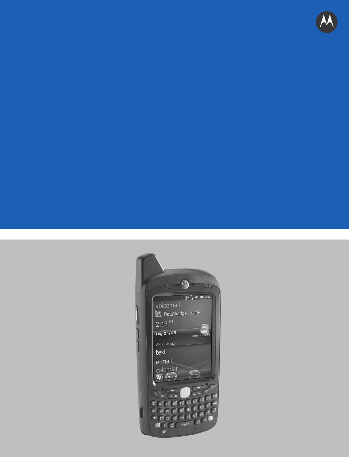
MC67 USER GUIDE
MC67 USER GUIDE 72E-161697-02 Rev.
ii MC67 User Guide No part of this publication may be reproduced or used in any form, or by any electrical or mechanical means, without permission in writing from Motorola. This includes electronic or mechanical means, such as photocopying, recording, or information storage and retrieval systems. The material in this manual is subject to change without notice. The software is provided strictly on an “as is” basis. All software, including firmware, furnished to the user is on a licensed basis.
iii Revision History Changes to the original guide are listed below: Change Date Description -01 Rev. A 09/19/12 Initial release. -02 Rev. A 08/30/13 Add CDMA WAN support.
iv MC67 User Guide
TABLE OF CONTENTS Revision History .............................................................................................................................. iii About This Guide Introduction ..................................................................................................................................... Documentation Set ................................................................................................................... Configurations.................................
vi MC67 User Guide Turning Off the Radios ............................................................................................................. 1-10 Chapter 2: Using the MC67 Introduction .................................................................................................................................... Features ......................................................................................................................................... LED Indicators ..................
Table of Contents Video Configuration ................................................................................................................. 3-8 Viewing Pictures and Videos ......................................................................................................... 3-9 Customizing Pictures & Videos ...................................................................................................... 3-9 Chapter 4: Making Calls Introduction ..........................................
viii MC67 User Guide Text Messaging ............................................................................................................................. Viewing Text Messages ........................................................................................................... Sending a Text Message ......................................................................................................... Using a Dual Line SIM ...................................................................
Table of Contents Pairing with Discovered Device(s) ........................................................................................... Bluetooth Settings .................................................................................................................... Device Info ......................................................................................................................... Services ........................................................................................
x MC67 User Guide Chapter 10: Accessories Introduction .................................................................................................................................... Accessories ................................................................................................................................... Single Slot USB Cradle .................................................................................................................. Charging the MC67 Battery ..............
Table of Contents Housing .............................................................................................................................. Display ............................................................................................................................... Scanner Exit Window ......................................................................................................... Connector ......................................................................................
xii MC67 User Guide
ABOUT THIS GUIDE Introduction This guide provides information about using the MC67 mobile computer and accessories. NOTE Screens and windows pictured in this guide are samples and can differ from actual screens. Documentation Set The documentation set for the MC67 provides information for specific user needs, and includes: • MC67 Quick Start Guide - describes how to get the MC67 up and running. • MC67 User Guide - describes how to use the MC67.
xiv MC67 User Guide Configurations This guide covers the following configurations: Radios Display Memory Data Capture Options Operating System MC67NA WLAN: 802.11 a/b/g/n WPAN: Bluetooth v2.1 EDR WWAN:GSM/UMTS GPS: Stand-alone GPS or A-GPS 3.5” VGA Color 512 MB RAM/ 2 GB Flash 2D imager or 2D imager and camera Windows Embedded Handheld 6.5 Numeric, QWERTY, QWERTZ, AZERTY, PIM or DSD MC67ND WLAN: 802.11 a/b/g/n WPAN: Bluetooth v2.
About This Guide Tap xv > Wireless Companion > Wireless Status > Versions. Phone Software To determine the Phone software version: Press > > Phone information. Chapter Descriptions Topics covered in this guide are as follows: • Chapter 1, Getting Started provides information on getting the MC67 up and running for the first time. • Chapter 2, Using the MC67 provides basic instructions for using the MC67, including powering on and resetting the MC67.
xvi MC67 User Guide • Bullets (•) indicate: • Action items • Lists of alternatives • Lists of required steps that are not necessarily sequential • Sequential lists (e.g., those that describe step-by-step procedures) appear as numbered lists. Related Documents • MC67 Quick Start Guide, p/n 72-116172-xx. • MC67 Regulatory Guide, p/n 72-116171-xx. • MC67 Integrator Guide, p/n 72E-161698-xx. • Mobility Services Platform User Guide, p/n 72E-100158-xx.
About This Guide xvii If the problem cannot be solved by Motorola Solutions Global Customer Support, the user may need to return the equipment for servicing and will be given specific directions. Motorola Solutions is not responsible for any damages incurred during shipment if the approved shipping container is not used. Shipping the units improperly can possibly void the warranty. Remove the SIM card and/or microSD card from the MC67 before shipping for service.
xviii MC67 User Guide
CHAPTER 1 GETTING STARTED Introduction This chapter lists the parts and accessories for the MC67 and explains how to set up the MC67 for the first time. Unpacking Carefully remove all protective material from the MC67 and save the shipping container for later storage and shipping. Verify that the following were received: • MC67 mobile computer • 3600 mAh Lithium-ion battery • stylus with tether (installed) • Regulatory Guide • Quick Start Guide. Inspect the equipment for damage.
1-2 MC67 User Guide Getting Started To start using the MC67 for the first time: 1. Install a micro secure digital (SD) card (optional) 2. Install the subscriber identification module (SIM) card (GSM/UMTS only) 3. Install the battery. 4. Charge the MC67. 5. Power on the MC67. Installing a microSD Card The microSD card slot provides secondary non-volatile storage. The slot is located under the battery pack.
Getting Started 1-3 microSD card Holding tab Figure 1-2 Insert microSD Card in Holder 7. Close the card holder door and push down until it is securely in place. 8. If installing a SIM card, proceed to Installing the SIM Card. 9. Close the SIM card holder door and slide down until it locks into place. 10. Close the rubber access door. Installing the SIM Card NOTE GSM/UMTS networks only. Global System for Mobile communications (GSM) phone service requires a SIM card.
1-4 MC67 User Guide Figure 1-3 Lifting the SIM Cover 4. Insert the SIM card, as shown in Figure 1-4 ensuring that the card slides into the holding tabs on each side of the door. Figure 1-4 Inserting the SIM Card 5. Close the SIM card holder door and slide down to lock into place. 6. Close the rubber access door. 7. Install the battery. Installing the Battery To install the battery. 1. Insert the battery, bottom first, into the battery compartment in the back of the MC67. 2.
Getting Started 1-5 Battery Release Latch 2 1 Battery Figure 1-5 Inserting the Battery Charging the Battery CAUTION Ensure to follow the guidelines for battery safety described in Battery Safety Guidelines on page 11-2. Charging the Main Battery Before using the MC67 for the first time, charge the main battery until the amber Charging/Battery Status light emitting diode (LED) remains lit (see Table 1-1 on page 1-6 for charge status indications).
1-6 MC67 User Guide To charge the main battery: 1. Connect the charging accessory to the appropriate power source. 2. Insert the MC67 into a cradle or attach to a cable. The MC67 begins charging. The Charging/Battery Status LED blinks amber while charging, then turns solid amber when fully charged. See Table 1-1 for charging indications. The 3600 mAh battery charges in less than six hours. Table 1-1 LED Charge Indicators Charging/Battery Status LED Indication Off MC67 is not charging.
Getting Started 1-7 Calibrating the Screen NOTE The Calibration screen can be accessed by pressing Blue key then Backspace key. On the Personal Information Manager (PIM) keypad, tap Settings > System > Screen > Align Screen. To calibrate the screen so the cursor on the touch screen aligns with the tip of the stylus: 1. Remove the stylus from its holder on the side of the MC67. 2. Carefully press and briefly hold the tip of stylus on the center of each target that appears on the screen. 3.
1-8 MC67 User Guide 7. Lift the battery from the MC67. 8. Insert the replacement battery, bottom first, into the battery compartment in the back of the MC67. 9. Press the battery down until the battery release latch snaps (two clicks) into place. 10. Replace the handstrap. Replacing the microSD Card CAUTION The MC67 backup battery retains data for up to 15 minutes. Replace the battery within 15 minutes to ensure that application states are maintained and that data is not lost.
Getting Started 1-9 To replace a SIM card: 1. If the MC67 is in a cradle, remove it before performing a Safe Battery Swap. 2. If the MC67 is in suspend mode, press the red Power button to wake the device. 3. Press the red Power button. The Power Action Key window appears. 4. Tap Safe Battery Swap. The Data Capture LED lights red. 5. When the LED turns off, remove the handstrap. 6. Remove the battery. 7. Lift the rubber access door. 8. Slide SIM card holder door up to unlock. 9.
1 - 10 MC67 User Guide Changing the Backlight Settings To change the backlight settings in order to conserve more battery power: 1. Tap > Settings > System > Backlight > Battery Power. 2. Select the Disable backlight if device is not used for check box and select a value from the drop-down list. 3. Select the Brightness tab. 4. Tap the Disable backlight check box to turn off the display backlight, or use the slider to set a low value for the backlight. 5. Select OK.
Getting Started 1 - 11 2. Tap Start > Settings > Connections > Network Setup & Activation. The Network Setup & Activation window displays. Figure 1-7 Network Setup and Activation Setup Window 3. Tap Switch to CDMA. 4. The window closes. 5. Tap Network Setup & Activation. 6. Tap Activation. The CDMA Activation window appears. 7. Tap Start Activation and PRL Update. 8. Follow the on-screen instructions.
1 - 12 MC67 User Guide 3. The window closes. 4. Tap Network Setup & Activation. NOTE Switching radio bands may not be available on all networks. 5. In the GSM/UMTS Settings drop-down list, select connection type. Options: a. Auto (GSM&UTMS) b. GSM Only c. UMTS Only. 6. Tap Apply GSM/UMTS Settings. 7. Tap OK. Switching from GSM/UTMS to CDMA 1. Tap Start > Settings > Connections > Network Setup & Activation. The Network & Activation window appears. 2. Tap Switch to CDMA. 3.
CHAPTER 2 USING THE MC67 Introduction This chapter explains the buttons, status icons, and controls on the MC67, and provides basic instructions for using the MC67, including resetting the MC67 and entering data.
2-2 MC67 User Guide Battery Battery Latch Speaker Camera Flash Handstrap Camera Stylus Stylus Clip Action Button Scan/Action Button Exit Window Figure 2-2 MC67 Rear View LED Indicators The MC67 has three light emitting diode (LED) indicators. The Data Capture LED indicates status for scanning. The Charging/Battery Status LED indicates battery charging and status.The Radio Status LED indicates Wide Area Network (WAN) radio status. Table 2-1 describes the LED indications.
Using the MC67 2-3 Table 2-1 LED Indications (Continued) LED State Indication Flashing Green Software initiated notification. Solid Red (after Safe Battery Swap mode) MC67 is shutting down for battery replacement. Off Data capture not enabled. Charging/Battery Status LED Slow Blinking Amber Main battery in MC67 is charging. Solid Amber Main battery in MC67 is fully charged. Fast Blinking Amber Charging error. Off MC67 not charging.
2-4 MC67 User Guide Finger Scrolling Finger scrolling can be used to scroll up and down web pages, documents, and lists such as the contacts list, file list, message list, calendar appointments list, and more. When finger scrolling, swipe or flick a finger on the screen. To scroll down, swipe a finger upward on the screen. To scroll up, swipe a finger downward on the screen. To auto-scroll, flick a finger upward or downward on the screen. Touch the screen to stop scrolling.
Using the MC67 2-5 Figure 2-6 Moving Today Screen Also touch and hold the Information Status bar and move it up and down over an application name. Remove finger and the Information Status bar and application name center in the screen. Figure 2-7 Moving Information Status Bar Application Icon Application Information Figure 2-8 Information Bar Example To customize the Home screen, tap > Settings > Today.
2-6 MC67 User Guide Classic Today Screen The user can change to the classic Today screen layout that is used in Windows Mobile 6.1. Status Bar Today Screen Task Tray Tile Bar Figure 2-9 Classic Today Screen To change to the classic view tap > Settings > Home > Items. Figure 2-10 Home Screen Settings Deselect the Windows Default checkbox and select any of the other checkboxes. Tap . The task bar at the bottom of the screen can contain the task tray icons listed in Table 2-2.
Using the MC67 2-7 Table 2-2 Task Tray Icons Icon Name Description Wireless connection status Wireless connection status icon. Indicates wireless local area network (WLAN) signal strength and opens the Wireless Applications menu. Bluetooth Enabled The Bluetooth Enabled icon appears in the task tray and indicates that the Bluetooth radio is on (Displays only if the StoneStreet One Bluetooth stack is enabled).
2-8 MC67 User Guide Table 2-3 Status Bar Icons (Continued) Icon Description Icon Description Connectivity Connection is active. Connection is not active. Synchronization is occurring. wireless fidelity (Wi-Fi) available. Wi-Fi in use. HSPA+ available. 3G available. GPRS available. EGPRS available. Roaming. Call missed. Dialing while no SIM card is installed. Call in progress. Calls are forwarded. Call on hold. Speakerphone is on. Phone on/good signal. Phone off. No WAN service.
Using the MC67 Icon Bar Figure 2-12 Icon Bar Table 2-4 Task Tray Icons Icon Name Description Magnify Enlarges the screen. Voicemail Dials Voicemail. Missed Call Opens the Call History window and displays a list of missed calls. Low Backup Battery Indicates that the backup battery is low. Notifications Indicates that notifications are available. Headset Indicates that a wireless stereo headset is connected to the MC67. Connectivity Displays the Connectivity dialog box.
2 - 10 MC67 User Guide Tile Bar The Tile Bar, located at the bottom of the screen, contains the Start tile displays tiles that vary depending upon the open application. to open the Start Menu. It also Figure 2-13 Tile Bar Examples Table 2-5 Programs Available on the Start Menu Icon Description Icon Description Home - Closes the Start menu and displays the Home screen. Text - Send an text message. Phone - Make calls. E-mail - Send an Email. Contacts - Keep track of friends and colleagues.
Using the MC67 2 - 11 Table 2-5 Programs Available on the Start Menu (Continued) Icon Description Icon Description ActiveSync - Synchronize information between the MC67 and a host computer or the Exchange Server. File Explorer - Organize and manage files on the device. Internet Sharing - Connect a notebook computer to the Internet using the MC67's data connection. Search Phone - Search contacts, data, and other information on the MC67.
2 - 12 MC67 User Guide Adjusting Volume To adjust the system volume: 1. Press the volume buttons on the right side of the MC67 to increase and decrease the system volume. The Volume dialog box appears. 2. As the user increases or decreases the volume, the slider moves accordingly. The user can also move the slider to adjust the volume. 3. Select the Vibrate radio button to turn off the system audio and enable the MC67 to vibrate upon system notifications. 4.
Using the MC67 2 - 13 Figure 2-14 Unlock Device Window If the MC67 was locked with a PIN or password, a prompt appears. Un-locking with Simple PIN When the MC67 is locked, the Lock screen appears. Figure 2-15 Simple PIN Lock Screen Enter the password to un-lock the device. Tap the Unlock button to unlock the device and go to the Home screen, or tap the Contact button to unlock the device and go to the Contacts window or tap the Email button to unlock the device and go to the Messaging window.
2 - 14 MC67 User Guide Figure 2-16 Strong Password Lock Screen Enter the strong password and then tap Unlock. NOTE If the user enters an incorrect password eight times, the user is requested to enter a code before trying again. If the user forgets the password, contact the system administrator. Battery Status Indications Battery icons appear on the Status bar indicating the battery power level.
Using the MC67 2 - 15 Figure 2-18 Settings Power Window Battery Reserve Options If the charge of the battery reaches a critical threshold, the MC67 shuts down. This threshold can be changed but affects the amount of time that data can be retained. 1. Tap > Settings > System > Power > RunTime. A warning message appears. Figure 2-19 Warning Message 2. Read the warning message and tap OK.
2 - 16 MC67 User Guide 3. Select one of the Battery Reserve Options. • Option 1: Minimum - After a low battery shutdown, data will be retained for minimum amount of time. Battery should be replaced immediately to avoid data loss. • Option 2: Less - After a low battery shutdown, data will be retained for less than normal amount of time. • Option 3: Normal - After a low battery shutdown, data will be retained for maximum amount of time. 4. Tap OK.
Using the MC67 2 - 17 NOTE The Temperature Warning dialog box remains visible until the user taps Hide. Interactive Sensor Technology The Interactive Sensor Technology (IST) supports the following features: • Power Management – manages power by configuring IST to control switching on/off the backlight, control suspend mode of the MC67 by monitoring motion and orientation. • Display Orientation – switches the screen orientation to either landscape or portrait depending on the MC67 orientation.
2 - 18 MC67 User Guide than 450 ms, which may indicates nearly a one meter drop. This data can be used as an indicator of potential abuse or misuse. IST features a log for recording the free fall events. This log records the date, time and the time period of the free fall. Stylus Use the MC67 stylus to select items and enter information. The stylus functions as a mouse. • Tap: Touch the screen once with the stylus to press option buttons and open menu items.
Using the MC67 2 - 19 Using Voice-Over-IP The MC67 supports Voice over IP over WLAN (VoWLAN) using third party voice clients. The MC67 can communicate using VoIP either using the MC67 supports several audio outputs, including back speaker phone, front receiver or handset, and Bluetooth headset. It is recommended that the wireless network use the 802.11a (5 GHz) band for voice applications. Using the 5 GHz band avoids some noise sources that may occur on the 802.11b/g (2.
2 - 20 MC67 User Guide
CHAPTER 3 DATA CAPTURE Introduction The MC67 offers three types of data capture options: • Imaging • Digital camera. Imaging The MC67 with an integrated imager has the following features: • Omnidirectional reading of a variety of bar code symbologies, including the most popular linear, postal, PDF417, and 2D matrix code types. • The ability to capture and download images to a host for a variety of imaging applications.
3-2 MC67 User Guide required bar code to decode only this bar code. This feature is ideal for pick lists containing multiple bar codes and manufacturing or transport labels containing more than one bar code type (either 1D or 2D). • Image Capture Mode: Use this mode to capture an image within the MC67’s field of view. This is useful for capturing signatures or images of items like damaged boxes.
Data Capture 2. Launch an application that supports text inputs, such as Word Mobile 2010 or Excel Mobile 2010. 3. Point the exit window on the top of the MC67 at a bar code. 3-3 Figure 3-1 Imager Scanning 4. Press and hold the scan button. The red laser aiming pattern turns on to assist in aiming. Ensure the bar code is within the area formed by the crosshairs in the aiming pattern. The aiming dot is used for increased visibility in bright lighting conditions.
3-4 MC67 User Guide Digital Camera Scanning To read a bar code, a scan-enabled application is required. The MC67 contains the DataWedge application that allows the user to enable the camera, decode the bar code data and display the bar code content. 1. Enable DataWedge. See Enable DataWedge on page 3-4. 2. Launch an application that supports text inputs, such as Word Mobile 2010 or Excel Mobile 2010. 3. Point the camera lens on the back of the MC67 at a bar code. Figure 3-4 Camera Scanning 4.
Data Capture 5. Ensure that a check mark is next to 1. Enabled. If not, tap 1. Enabled. 6. Tap 0. Back. 7. Tap 0. Back. 8. Tap 0. Exit and then tap OK. 9. Tap Running to start the DataWedge process. The DataWedge Status changes to Ready. 3-5 10. Tap OK. Disable DataWedge To disable DataWedge: 1. Tap > Settings > System > DataWedge. 2. Tap the Running option to end the DataWedge process. The DataWedge Status changes to Stopped. 3. Tap OK. Taking Pictures To take a picture: 1.
3-6 MC67 User Guide 1. Tap > Pictures & Videos. 2. Tap Camera. 3. Tap Menu > Mode > Burst. 4. Check the image on the view finder, adjust if necessary. 5. Press the Enter key to take the picture. To stop a burst of pictures before all pictures have been taken tap OK. Timer Mode To take pictures using the timer: 1. Tap > Pictures & Videos. 2. Tap Camera. 3. Tap Menu > Mode > Timer. NOTE By default, the self timer delay is set at five seconds. 4.
Data Capture 1. Tap 2. Tap Menu, then configure the device settings. 3-7 > Pictures & Videos. • Video - Tap to switch to video mode. • Mode - Select from the following modes to take the picture: Normal - Takes picture using the default settings. Burst - Takes picture consecutively in continuous mode. • Timer - Takes picture five seconds after pressing the Enter key. • • • Brightness - Set the camera brightness level. • Resolution - Set the camera resolution level.
3-8 MC67 User Guide 5. Press the Enter key to stop recording. Video Configuration To configure the video settings: 1. Launch the Video application. 2. Tap Menu, then configure the device settings. • Still - Tap to switch to still (camera) mode. • Brightness - Set the video brightness level. • Quality - Set the quality (video resolution and sound fidelity) and size of the video clips. Video clips of higher quality require more memory.
Data Capture 2. 3-9 On the General tab, set the following options: • Select the size of the pictures to send through e-mail. Only pictures sent through an e-mail message is resized, the original picture remains unchanged. • Resize pictures for faster e-mail transfer. • Rotate pictures towards left or right. 3. On the Slide Show tab, set the following options: • Select the Portrait pictures or Landscape pictures radio button to set slide show orientation.
3 - 10 MC67 User Guide
CHAPTER 4 MAKING CALLS Introduction Use the MC67 to make phone calls, keep track of calls, and send text messages. Wireless service providers may also provide other services such as voice mail, call forwarding, and caller ID. Also use the phone to connect to an Internet Service Provider (ISP) or work network in order to browse the Web and read e-mail over Evolved High-Speed Packet Access (HSPA+) or CDMA Evolution Data Optimized (EvDO) using cellular line.
4-2 MC67 User Guide Smart Dialing Smart Dialing makes it easy to dial a phone number. When the user starts entering numbers or characters, Smart Dialing automatically searches and sorts the contact entries on the SIM card, in Contacts, and the phone numbers in Call History (including incoming, outgoing, and missed calls). The user can then select the desired number or contact from the filtered list to dial.
Making Calls 4-3 Using Contacts Use Contacts to make a call without looking up or entering the phone number. To make a call from Contacts: 1. Tap Contacts. 2. From the contact list, tap and hold the contact name. Figure 4-2 Contacts Menu 3. Tap Call Work, Call Home or Call Mobile. NOTE To make a call from an open contact, tap the number to call. See On-Device Help for more information about Contacts. Using Call History To make a call using Call History: 1. Press . 2.
4-4 MC67 User Guide 4. Tap End or press the red phone key on the MC67 keypad to stop dialing or end the call. Making a Speed Dial Call Use Speed Dial to call someone saved in the speed dial directory. To make a speed dial call: 1. Press . 2. From the keypad, tap and hold the speed dial location number assigned to a contact. (To dial a one-digit speed dial location number, tap and hold the speed dial number.
Making Calls 4-5 • The user can use other programs on the MC67 during a call. To switch back to the phone, press . To end the call press ok . Incoming Call Features Press to end the call. ok • To hold the current call and answer a waiting call, tap Answer to place the current call on hold and answer the incoming call. • Press to put a call on hold to call another number. • To move from one call to another, press .
4-6 MC67 User Guide appropriately before putting the headset on. When a Bluetooth headset is connected the speakerphone is muted. Adjusting Audio Volume Use the Volume buttons to adjust the volume of the ringer when not in a call and the audio volume when in a call. NOTE Adjust the conversation phone volume during a call. Adjusting the volume while not in a call affects the ring and notification sound levels.
Making Calls 4-7 Using Call History Use Call History to call someone who was recently called, or recently called in. Call History provides the time and duration of all incoming, outgoing, and missed calls. It also provides a summary of total calls and easy access to notes taken during a call. Table 4-1 lists the call history icons that appear in the Call History window. Table 4-1 Call History Icons Icon Description This icon appears next to the contact information for all outgoing calls.
4-8 MC67 User Guide Figure 4-7 Call History - Call Timers 5. Tap Reset. (The All Calls: counter cannot be reset.) 6. Tap OK to exit the Call Timers window. Deleting All Call History Items 1. Press to display the Phone dialer. 2. From the Phone dialer, tap Call History. 3. Tap 4. Select Delete all calls. 5. Tap Yes. 6. Tap OK to exit the Call History window. . Viewing Call Status 1. Press to display the Phone dialer. 2. From the Phone dialer, tap Call History. 3. Tap an entry.
Making Calls 4-9 NOTE When more than one call is on the phone line, only the duration of the first call is recorded. 4. Tap OK and then OK to exit. Using the Call History Menu Use the Call History menu to dial voice mail, save to contacts, view a note, delete a listing, send an SMS and make a call. 1. Press to display the Phone dialer. 2. From the Phone dialer, tap Call History. 3. Tap and hold an item in the list. Figure 4-9 Call History - Menu 4.
4 - 10 MC67 User Guide 5. After the call is answered, tap Conference to place the calls in conference mode. 6. Tap Hold to place the conference on hold. 7. Enter another phone number and tap Talk. 8. After the call is answered, tap Conference to place all the calls in conference mode. 9. Repeat steps 6 through 8 for up to six phone numbers. 10. Tap End or press the red phone key on the keypad to end the conference call. NOTE To speak privately with one party during a conference call, tap Private.
Making Calls 4 - 11 Figure 4-10 Call Swapping - Hold 3. Tap Hold on to place the first number on hold. 4. Enter the second number and tap Talk. Figure 4-11 Call Conferencing - Conferencing 5. Tap Swap to move from one call to the other. 6. Tap End or press the red phone key on the MC67 keypad to end each call. Swapping Calls (CDMA) NOTE For use with CDMA networks only. To swap between two incoming phone calls: 1. Tap Answer (icon) to connect to the first call.
4 - 12 MC67 User Guide Figure 4-12 Answer a Call 2. When a second call arrives, tap Answer (icon). The first call is placed on hold. 3. Tap Talk to swap from one call to the other. Figure 4-13 Call Swapping 4. Tap End or press the red phone key on the keypad to end the active call. The remaining call re-connects, 5. Tap End or press the red phone key on the keypad to end the last call. Speed Dial Setup Create speed dial numbers to dial frequently called numbers with a single tap.
Making Calls 4 - 13 Figure 4-14 Contacts 4. Tap the desired contact name and number in the list. Figure 4-15 Speed Dial Contact Location 5. In the Location field, tap the up/down arrows to select an available location to assign as the new speed dial entry. The first speed dial location is reserved for voice mail. 6. Tap OK to add the contact to the speed dial list. Figure 4-16 Speed Dial Contact List 7. Tap OK to exit the Speed Dial Contact List.
4 - 14 MC67 User Guide 1. Tap > Contacts. Figure 4-17 Contacts 2. Tap a contact name. 3. Tap Menu > Add to Speed Dial. Figure 4-18 Speed Dial Contact Location 4. Tap the up/down arrows to select an available location to assign as the new speed dial entry. The first speed dial location is reserved for voice mail. 5. Tap OK. Editing a Speed Dial Entry To change a speed dial entry: 1. Press . 2. Tap Speed Dial button.
Making Calls 4 - 15 Figure 4-19 Speed Dial Contact List 3. Tap and hold the contact name. 4. Tap Edit... . 5. Change the name, phone number, or location information. 6. Tap OK. NOTE Editing names and phone numbers in Speed Dial does not alter contact information in Contacts ( Contacts). > Deleting a Speed Dial Entry To delete a speed dial entry: 1. Press . 2. Tap Speed Dial button. 3. Tap and hold the contact name. 4. Tap Delete. 5.
4 - 16 MC67 User Guide
CHAPTER 5 USING WLAN Introduction Wireless Local Area Networks (WLANs) allow the MC67 to communicate wirelessly inside a building. Before using the MC67 on a WLAN, the facility must be set up with the required hardware to run the WLAN (sometimes known as infrastructure). The infrastructure and the MC67 must both be properly configured to enable this communication. Refer to the documentation provided with the infrastructure (access points (APs), access ports, switches, Radius servers, etc.
5-2 MC67 User Guide Figure 5-1 Wireless Launch Window Refer to the Wireless Fusion Enterprise Mobility Suite User Guide for Version X2.xx for detailed information on using and configuring Fusion Wireless Companion. To access the on-device Fusion Help tap > Wireless Companion > Fusion Help. Connecting to the Internet To connect to the Internet on a WLAN when using Fusion Wireless Companion, ensure that the network card settings is set to Internet: 1.
Using WLAN 5-3 Table 5-1 Supported Applications (Continued) Application Description Options Invokes the Options application which allows the user to configure the Fusion option settings. Wireless Status Invokes the Wireless Status application which allows the user to view the status of the current wireless connection. Wireless Diagnostics Invokes the Wireless Diagnostics application which provides tools with which to diagnose problems with the wireless connection.
5-4 MC67 User Guide Figure 5-3 Operating Mode Dialog Box 7. Tap Next. The Security Mode dialog box displays. 8. In the Security Mode drop-down list, select Legacy (Pre-WPA). Figure 5-4 Security/Authentication Dialog Box 9. In the Authentication drop-down list, select None. 10. Tap Next. The Encryption dialog box displays. 11. In the Encryption Type drop-down list, select WEP-40 (40/24). Figure 5-5 Encryption Dialog Box 12.
Using WLAN 5-5 Figure 5-6 WEP-40 WEP Keys Dialog Box 15. In the Edit Key drop-down list, select the key to enter. 16. In the Key field, enter 10 hexadecimal characters. 17. In the Confirm field, re-enter the key. When the keys match, a message appears indicating that the keys match. 18. Repeat for each WEP key. 19. In the Transmit Key drop-down list, select the key to transmit. 20. Tap Next. The IPv4 Address Entry dialog box displays. Figure 5-7 IP Address Entry Dialog Box 21.
5-6 MC67 User Guide
CHAPTER 6 MESSAGING Introduction This chapter describes how to use Email and text messaging. Email Use email to send messages to other users. See Email Setup on page 6-6 for information on setting up an Email account. Creating an Email Message To create an email message: 1. Press > E-mail. 2. Select an email account. 3. Tap 4. To add recipients, enter their email addresses, separating them with a semicolon ( ; ). Tap To to add email addresses stored in Contacts. 5.
6-2 MC67 User Guide 2. Select an email account. 3. Tap an email to open it. Replying to a Message To reply to a message: 1. Press > E-mail. 2. Select an email account. 3. Tap an email to open it. 4. Tap 5. Enter a reply message, and then tap . . Text Messaging Use the Text Messages window to send and receive text messages to and from mobile phones. The text can contain words, numbers, or an alphanumeric combination no longer than 160 characters.
Messaging Figure 6-2 New Text Message Options When the phone function is off, the user can still view received text message: 1. Tap > Text or on the Today screen, tap the text message on the Information Bar. Tap to View Text Messages. Figure 6-3 Text Messaging on Today Screen 2. The Text Messages window appears. 3. In the message list, tap the text message. Enter reply here.
6-4 MC67 User Guide NOTE If the phone is turned off and the user tried to call the sender, send a reply, or forward the message, the user is prompted to turn the phone function on. Sending a Text Message To create a text message: 1. On the Phone screen, select a contact name to send a message to. 2. Tap Menu > Send Text Message. Figure 6-5 Phone Screen Contact List 3. Compose the message.
Messaging 6-5 If the user is out of coverage area, the message is saved in the Drafts folder. The user has to manually re-send it when the user returns to a coverage area. NOTE Using a Dual Line SIM NOTE Check with the service provider for availability. Dual line SIM cards allow for two phone lines on a single card. For example, one line can be a business phone line and the other a personal phone line. To switch between phone lines: 1. Tap > Programs > SIM Toolkit. Figure 6-7 SIM UI Window 2.
6-6 MC67 User Guide Email Setup The MC67’s Messaging application lets users access and manage multiple email accounts simultaneously in one convenient location. To send and receive email messages through an ISP (Internet Service Provider) account, or to use the MC67 to access corporate email through a VPN (Virtual Private Network), first set up an IMAP or POP account.
Messaging 6-7 11. Tap Next. 12. Tap the Automatic Send/Receive: field and select the time interval for the MC67 to send and check for new email messages. 13. Tap the Review all download settings link for additional download settings and options. See Editing an Email Account on page 6-8 for more details. 14. Tap Finish.
6-8 MC67 User Guide 15. In the User name: field enter the username for the account. 16. In the Password: field enter the password for the account. 17. Tap Next. 18. In the Outgoing (SMTP) mail server: field enter the outgoing mail server address. 19. Check the appropriate fields and then tap OK. • Outgoing server requires authentication is used if a password is required for outgoing mail in addition to incoming mail. (Please contact the System Administrator for detailed server requirements.
Messaging 6-9 • Require SSL for Incoming e-mail check box to enable SSL encryption of incoming email (if supported by the mail server). • Require SSL for Outgoing e-mail checkbox to enable SSL encryption of outgoing email (if supported by the mail server). • Network connection drop-down list to select a firewall connection setting. Select either The Internet (open: no firewall), Work (behind a firewall) or a data connection. 11. Tap Done and then tap Next. 12.
6 - 10 MC67 User Guide
CHAPTER 7 BLUETOOTH Introduction Bluetooth-equipped devices can communicate without wires, using frequency-hopping spread spectrum (FHSS) radio frequency (RF) to transmit and receive data in the 2.4 GHz Industry Scientific and Medical (ISM) band (802.15.1). Bluetooth wireless technology is specifically designed for short-range (10 meters/32 feet) communication and low power consumption. MC67s with Bluetooth capabilities can exchange information (e.g.
7-2 MC67 User Guide The Bluetooth radio in this MC67 operates as a Class 2 device power class. The maximum output power is 2.5mW and the expected range is 10 meters (32 feet). A definition of ranges based on power class is difficult to obtain due to power and device differences, and whether one measures open space or closed office space. NOTE It is not recommended to perform Bluetooth wireless technology inquiry when high rate 802.11b operation is required.
Bluetooth 7-3 FIPS 140-2 The MC67 supports FIPS 140-2 for Bluetooth using the Microsoft Bluetooth stack and the StoneStreet One Bluetooth stack. FIPS provides secure Bluetooth communication between the MC67 and another mobile computer or scanner only using a Serial Port Profile. Bluetooth Configuration By default, the MC67 is configured to using the Microsoft Bluetooth stack. Refer to the MC67 Integrator Guide, Appendix B, for information on switching to the StoneStreet One Bluetooth stack.
7-4 MC67 User Guide Table 7-2 COM Ports Microsoft Bluetooth Stack StoneStreet One Bluetooth Stack COM5 COM5 COM9 COM9 FIP2 COM11 COM21 COM22 COM23 FIP2 Bluetooth Power States Cold Boot Performing a cold boot retain the state of the Bluetooth radio prior to the cold boot. Warm Boot Performing a warm boot retain the state of the Bluetooth radio prior to the warm boot.
Bluetooth 7-5 MotoBTUI Application Use the MotoBTUI application to: • Turn the Bluetooth radio on and off. See Turning the Bluetooth Radio Mode On and Off on page 7-6. • View device information • Control device status • Generate a pairing bar code (See Using the RS507 Hands-free Imager on page 10-19 for more information). • Configure FIPS key. Figure 7-1 MotoBTUI Window Device Information The view the MC67 Bluetooth information: 1. Tap Start > MotoUI. 2. Tap My Device Information. 3.
7-6 MC67 User Guide To generate a new FIPS key automatically: 1. Tap Start > MotoUI. 2. Tap FIPS Configuration. 3. Tap Generate Key button. 4. Tap the SetUp Key button. A new key is generated. The key file, NewAESKey.reg, is created in the /Application folder. 5. Tap the Back button to return to the MotoBTUI window. To generate a new FIPS key manually: 1. Tap Start > MotoUI. 2. Tap FIPS Configuration. 3. Tap Enter Key button. 4. In the text box, enter a key. 5. Tap the SetUp Key button.
Bluetooth 7-7 exchange information with other Bluetooth devices (within range). Communicate only with Bluetooth radios in close proximity. NOTE To achieve the best battery life turn off radios not in use. Enabling Bluetooth There are three ways to enable Bluetooth: 1. Microsoft Bluetooth application: a. Tap > Setting > Connections > Bluetooth > Mode. Figure 7-2 Bluetooth Mode 2. 3. b. Check the Turn On Bluetooth checkbox to turn on the Bluetooth radio on. c. Tap OK. Wireless Manager: a.
7-8 MC67 User Guide 2. 3. b. Un-check the Turn On Bluetooth checkbox to turn the Bluetooth radio off. c. Tap OK. Wireless Manager: a. Tap the Status Bar. b. Tap the Connectivity icon. c. Tap Wireless Manager. d. Tap Bluetooth to turn the Bluetooth radio off. e. Tap X. MotoBTUI application: a. Tap > MotoBTUI. b. Tap the Bluetooth On tab to turn the Bluetooth radio off. c. Tap X. Discovering Bluetooth Device(s) The MC67 can receive information from discovered devices without pairing.
Bluetooth Figure 7-4 Searching for Bluetooth Devices 6. Select a device from the list. Figure 7-5 Select a Bluetooth Device 7. Tap Next. The Enter Passcode window appears. NOTE If Smart-pairing is configured and the device is requesting one of the pre-defined PINs, the Enter Passcode window does not appear.
7 - 10 MC67 User Guide 8. Enter a Passcode. If the device has a specific passcode, enter it in the Passcode field and tap Next. If the device does not have a specific passcode, enter one in the Passcode field and tap Next. The MC67 tries to connect with the other device. 9. If you created a passcode, you will be prompted by the other device to enter the same passcode. Enter the created passcode to establish a paired connection.
Bluetooth 7 - 11 Figure 7-7 File Explorer Window 6. Select Beam File. The MC67 searches for Bluetooth devices in the area. 7. Tap Tap to send next to the Bluetooth device to send the file to. The MC67 communicates with the device and sends the file. When completed, Tap to send changes to Done. Figure 7-8 Beam File Window To transfer a contact between the MC67 and another Bluetooth enabled device: 1. Ensure that Bluetooth is enabled and discoverable on both devices. 2.
7 - 12 MC67 User Guide Figure 7-9 Contact Window 6. Select Send Contact > Beam. The MC67 searches for Bluetooth devices in the area. 7. Tap Tap to send next to the Bluetooth device to send the file to. The MC67 communicates with the device and send the contact. When completed, Tap to send changes to Done. Internet Sharing Internet Sharing allows the user to connect a computer or laptop to the MC67 and use the MC67 as a modem to connect to an office network or Internet Service Provider (ISP).
Bluetooth 7 - 13 Serial Port Services Use the wireless Bluetooth serial port connection as a physical serial cable connection. Configure the application that will use the connection to the correct serial port. To establish a serial port connection: 1. Ensure that Bluetooth is enabled and discoverable on both devices. 2. Ensure that the two devices are within 30 feet (10 meters) of one another. 3. Tap 4. Tap Add new device. The MC67 begins searching for discoverable Bluetooth devices in the area. 5.
7 - 14 MC67 User Guide NOTE For additional security, disable network bridging on the computer (specifically, bridging to a Remote NDIS adapter) before connecting to the computer to pass though to the Internet or a network. For more information on network bridging, see Windows Help on the computer. Refer to the Windows Help for instructions on setting up a Bluetooth connection. 1. Ensure that Bluetooth is enabled and discoverable on both devices. 2.
Bluetooth 7 - 15 3. Tap > Settings > Connection > Bluetooth > Devices. 4. Tap Add New Device.The MC67 searches for a Bluetooth device, such as a Car Kit. 5. Select a device from the list. 6. Tap Next. The Enter Passcode window appears. NOTE If Smart-pairing is configured and the device is requesting one of the pre-defined PINs, the Enter Passcode window does not appear. 7. Enter the Passcode and the tap Next. The device is added to the Bluetooth list. 8.
7 - 16 MC67 User Guide Using Bluetooth StoneStreet One Bluetooth Stack The following sections provide information on using the Stone Street One Bluetooth stack. Turning the Bluetooth Radio Mode On and Off Turn off the Bluetooth radio to save power or if entering an area with radio restrictions (e.g., an airplane). When the radio is off, other Bluetooth devices cannot see or connect to the MC67. Turn on the Bluetooth radio to exchange information with other Bluetooth devices (within range).
Bluetooth 7 - 17 Figure 7-11 Explorer Mode Window Use the “tap and hold” technique to view available options. Scroll bars and view options are similar to those on the Windows desktop. The tree structure lists the following sub-items: • Local Device - This device • Remote Device - Other Bluetooth devices • Trusted Devices - Bonded (paired) Bluetooth devices • Untrusted Devices - Discovered devices that are not bonded • Favorites - Selected services that are set as Favorite for quick access.
7 - 18 MC67 User Guide Figure 7-12 BTExplorer Window 7. Select Explore Services on Remote Device or another from the drop-down list and tap Next. NOTE If a device discovery action has not been previously performed, a device discovery is automatically initiated. If a device discovery has previously been performed, the device discovery process is skipped, and the previously found list of devices displays.
Bluetooth 7 - 19 Figure 7-14 Select Remote Device Window 9. Select a device from the list and tap Next. The MC67 searches for services on the selected Bluetooth device. Figure 7-15 Device Services NOTE If the MC67 discovers a service but the service is not supported, the service icon is grayed-out. 10. Select a service from the list and press Next. The Connection Favorite Options window appears. Figure 7-16 Connection Favorite Options Window 11.
7 - 20 MC67 User Guide 12. Tap Next. The Connection Summary window appears. 13. Tap Connect to add the service to the Favorite window and connect to the service. Figure 7-17 Favorites Window Available Services NOTE Some devices might not require a PIN. This depends upon the device’s authentication. See the following sections for information on these services. File Transfer Services NOTE Shared folders are a security risk. To transfer files between the MC67 and another Bluetooth enabled device: 1.
Bluetooth 7 - 21 Figure 7-18 File Transfer Window 7. Double-tap the file to copy. The Save Remote File window appears. Figure 7-19 Save Remote File Window 8. Tap and hold on the file. A pop-up menu appears. 9. Select the action to perform: • New - create a new file or folder on the remote device • Delete - delete the selected file on the remote device. • Get File - copy the file from the remote device to the MC67. • Put File - copy a file from the MC67 to the remote device.
7 - 22 MC67 User Guide 1. Tap and hold on the file to delete and select Delete. 2. In the Delete Remote Device File dialog box tap Yes. Getting a File To copy a file from a remote device: 1. Double-tap or tap and hold on the file and select Get. The Save Remote File window appears. 2. Navigate to the directory to save the file. 3. Tap Save. The file is transferred from the remote device to the MC67. Copying a File To copy a file to a remote device: 1. Tap Action > Put.
Bluetooth 7 - 23 1. Ensure the Bluetooth Phone is discoverable and connectable. 2. Ensure that the Dial-Up Networking profile is enabled on the MC67. See Profiles on page 7-41 for more information. 3. Tap Menu > New Connection. 4. Select Explore Services on Remote Device or another from the drop-down list and tap Next. 5. BTExplorer searches for Bluetooth devices in the area. The discovered devices display in the Select Remote Device window. 6.
7 - 24 MC67 User Guide Figure 7-22 Select Dial-up Networking Entry Window 11. Select the entry and tap OK. The MC67 begins to communicate with the Bluetooth phone. If required, the phone requests permission to communicate with the MC67. 12. Confirm the connection on the phone. The Network Log On window appears. 13. In the User name text box, enter the user name for this connection. 14. In the Password text box, enter the password for this connection. 15.
Bluetooth 7 - 25 Figure 7-24 Add Phone Book Entry Window 3. In the Name for the connection text box, enter a name for this connection. 4. In the Country Code text box, enter the country code for the country that the user is calling. 5. In the Area Code text box, enter the area code. 6. In the Phone Number text box, enter the phone number. 7. Tap OK. Object Exchange Push Services Object Exchange (OBEX) is a set of protocols that allows sharing objects such as Contacts or pictures using Bluetooth.
7 - 26 MC67 User Guide NOTE Prior to sending and receiving contacts, a default contact must be set up before attempting to send a contact. 1. Tap and hold on OBEX Object Push and select Connect. Figure 7-25 OBEX Object Push Window 2. In the Action: drop-down list, select Send Contact Information. 3. Tap 4. Select a contact to send to the other device. 5. Tap OK. 6. Tap OK to send the contact to the other device and display a confirmation dialog box on the other device to accept the contact.
Bluetooth 7 - 27 Figure 7-26 OBEX Object Push Window 2. In the Action: drop-down list, select Swap Contact Information. 3. Tap 4. Select a contact to send to the other device. 5. Tap OK. 6. Tap OK to swap contacts with the other device and display a confirmation dialog box on the other device to accept the contact. 7. Tap Ok. . The Select Contact Entry window appears.
7 - 28 MC67 User Guide 3. Tap OK. The contact on the other device is copied. Sending a Picture To send a picture to another device: 1. Tap and hold on OBEX Object Push and select Connect. The OBEX Object Push window appears. Figure 7-28 OBEX Object Push Window 2. In the Action: drop-down list, select Send A Picture. 3. Tap . The Send Local Picture window appears. Figure 7-29 Send Local Picture Window 4. Navigate to the picture to send to the other device. 5. Tap Open. 6.
Bluetooth 7 - 29 NOTE Newer Bluetooth headsets are device dependant and remember the last device they connected to. If problems occur while connecting to the headset, place the headset in discovery mode. Refer to the headset user manual for more information. 1. Ensure the MC67 is connectable (required when automatic re-connect is initiated). See Device Info on page 7-34. 2. Ensure that the Headset profile is enabled on the MC67. See Profiles on page 7-41 for more information. 3.
7 - 30 MC67 User Guide Figure 7-30 ActiveSync Connection Settings Window on PC To establish an ActiveSync connection: NOTE When creating an ActiveSync connection, only use StoneStreet One Bluetooth Explorer in Wizard mode. 1. Use the Connection Wizard to search for a Bluetooth device, such as a computer. In the drop-down list select ActiveSync via Bluetooth. 2. Select the device and tap Next. The Connection Favorite Options window appears. 3. Tap Connect.
Bluetooth 7 - 31 Personal Area Network Services NOTE This profile supports Ad-hoc and PAN User. Network Access Profile is not supported. Connect two or more Bluetooth devices to share files, collaborate, or play multi-player games. To establish a Personal Area Network connection: 1. Ensure that the Personal Area Networking profile is enabled on the MC67. See Profiles on page 7-41 for more information. 2. Use the Connection Wizard to search for a Bluetooth device. 3. Select the device and tap Next.
7 - 32 MC67 User Guide 7. Tap Connect. Connect to a HID Device The MC67 can connect to an Human Interface Device (HID) device such as a Bluetooth keyboard: 1. Ensure the MC67 is connectable (required when automatic re-connect is initiated). See Device Info on page 7-34. 2. Ensure that the remote Bluetooth device is in discoverable mode. See the device user manual for instructions. 3. Ensure that the HID Client profile is enabled on the MC67. See Profiles on page 7-41 for more information. 4.
Bluetooth 7 - 33 Figure 7-32 Select Remote Device Window 5. Select a device from the list and tap Next. The PIN Code Request window appears. Figure 7-33 PIN Request Window 6. In the PIN Code field, enter the PIN code. 7. Tap OK. The Pairing Status window displays. 8. Tap Finish. The devices are successfully paired. The device name moves to the Trusted Devices window. Deleting a Paired Device To delete a device no longer needed: 1. Tap the Bluetooth icon and select Show BTExplorer.
7 - 34 MC67 User Guide Figure 7-34 PIN Code Request Window 2. In the PIN Code: text box, enter the same PIN entered on the device requesting the bond. The PIN must be between 1 and 16 characters. 3. In the Device Name: text box, edit the name of the device requesting the bond, if desired. 4. Tap OK to create the bond. The MC67 can now exchange information with the other device. Bluetooth Settings Use the BTExplorer Settings window to configure the operation of the BTExplorer application.
Bluetooth 7 - 35 Figure 7-35 BTExplorer Settings - Services To add a service: 1. Tap Add. Figure 7-36 Add Local Service Window 2. In the list, select a service to add. 3. Tap OK. The Edit Local Service window displays for the selected service. 4. Select the appropriate information and then tap OK. See the following sections for information on the available services. Dial-Up Networking Service Dial-up Networking allows other Bluetooth devices to access a dial-up modem.
7 - 36 MC67 User Guide Table 7-4 Dial-up Networking Information Data Item Description Local COM Port Select the COM port. Local Baud Rate Select the communication baud rate. Local Port Options Select the port option. File Transfer Service File transfer allows other Bluetooth devices to browse files. Figure 7-37 BTExplorer Settings - File Transfer Information Table 7-5 File Transfer Information Data Item Description Service Name Displays the name of the service.
Bluetooth 7 - 37 Table 7-7 Headset Audio Gateway Data Item Description Service Name Displays the name of the audio service. IrMC Synchronization Service The IrMC Synchronization service used to synchronize PIM contacts between a remote device and the MC67. Table 7-8 IrMC Synchronization Data Item Description Service Name Displays the name of the service. Service Security Select the type of security from the drop-down list. Options are None, Authenticate, or Authenticate/Encrypt.
7 - 38 MC67 User Guide Table 7-10 Personal Area Networking Data Item Description Service Name Displays the name of the service. Service Security Select the type of security from the drop-down list. Options are None, Authenticate, or Authenticate/Encrypt. Support Group Ad-Hoc Networking Select to enable Ad-Hoc networking. Serial Port Service Serial port allows other Bluetooth devices to access COM ports.
Bluetooth 7 - 39 Security Security settings allows the user to set global security policies for Bluetooth. Note that these settings are only active on local Services that are set to Authenticate or Authenticate/Encryption. The user can set authentication on local Services under Services. To adjust the security settings for an individual service, select Services first, then select the individual service, then Properties.
7 - 40 MC67 User Guide Figure 7-39 BTExplorer Settings - Discovery Table 7-15 Discovery Data Item Description Inquiry Length Sets the amount of time the MC67 takes to discover Bluetooth devices in the area. Name Discovery Mode Select either Automatic or Manual to automatically attempt to discover a Bluetooth device's name after finding the device. Discovered Devices - Delete Devices Deletes all discovered devices and link keys from memory.
Bluetooth 7 - 41 Provides support for devices such as mice, joysticks, keyboards. Table 7-17 HID Data Item Description Enable Key Repeat Enables key repeat functionality. Delay To increase key repeat delay, drag the Delay slider to the right. To decrease key repeat delay, drag the Delay slider to the left. Rate To increase key repeat speed, drag the Rate slider to the left. To decrease key repeat speed, drag the Rate slider to the right.
7 - 42 MC67 User Guide
CHAPTER 8 USING GPS NAVIGATION Introduction The MC67 includes Global Positioning System (GPS) technology. GPS technology is based on a worldwide system of GPS satellites orbiting the earth that continuously transmit digital radio signals. These radio signals contain data on the satellites’ locations and their exact clock time and are used to determine the user location on the earth.
8-2 MC67 User Guide 3. In the Hardware tab, the GPS hardware port is set to None. Operation Acquiring satellite signals may take several seconds to a few minutes. It is best to be outside and have a clear, unobstructed view of the sky. Without a clear view, acquisition takes much longer and could result in the MC67 being unable to compute the initial position quickly. When operating the device indoors access to the GPS signals may be limited or unavailable.
Using GPS Navigation 8-3 Figure 8-1 SUPL Setup Tab 2. Select Enable SET Initiated SUPL on Opening to enable the MC67 to initiate SUPL upon opening the GPS port. 3. Select Using Motorola Server to use the Motorola SUPL server. 4. Enter the SUPL Server IP address in the Server IP field. The server IP address is not required when using the Motorola server. 5. Enter the SUPL Server port number in the Port field. The port number is not required when using the Motorola server. 6.
8-4 MC67 User Guide
CHAPTER 9 SETTINGS This chapter provides information for customizing the MC67. Settings Folder Table 9-1 lists setting applications pre-installed on the MC67. Tap > Settings to open the Settings tab. Table 9-1 Setting Applications Icon Description Icon Description Clock & Alarms - Set the device clock to the date and time of the current location. Alarms can also be set at specified days and times of a week. Lock - Set a password for the MC67.
9-2 MC67 User Guide Table 9-1 Setting Applications (Continued) Icon Description Icon Description Bluetooth - Turn on Bluetooth, set the MC67 to visible mode and scan for other Bluetooth devices in the area. Domain Enroll - Make the device an AD domain member for device management and security. Wi-Fi - Setup wireless network connection and customize settings. USB to PC - Need info Wireless Manager - Enables or disables the MC67’s wireless radios and customizes Wi-Fi, Bluetooth and Phone settings.
Settings 9-3 Table 9-1 Setting Applications (Continued) Icon Description Icon Description Phone Info - Displays the MC67’s software and hardware information. Regional Settings - Set the regional configuration to use, including the format for displaying numbers, currency, date, and time on the MC67. Screen - Change the screen orientation, re-calibrate the screen, and change the screen text size. Remove Programs - Remove programs that were installed on the MC67.
9-4 MC67 User Guide Locking the MC67 Use the Password window to set a password to disable unauthorized access to the MC67. NOTE If the device is configured to connect to a network, use a strong (difficult to figure out) password to help protect network security. Password cracking tools continue to improve and the computers used to crack passwords are more powerful than ever. If the user enters an incorrect password eight times, the user is requested to enter a code before trying again.
Settings 9-5 2. Tap the Advanced tab. 3. Select the On battery power: Turn off device if not used for check box and select a value from the drop-down list. 4. Select OK. Backlight Settings To change the backlight settings: 1. Tap > Settings > System > Backlight > Battery Power tab. 2. Select the Disable backlight if device is not used for check box and select a value from the drop-down list. 3. Select the Brightness tab. 4. Tap the Backlight Auto Mode check box to disable auto mode. 5.
9-6 MC67 User Guide • USB On-the-Go - Sets the MC67 to automatically determine necessary mode (default). To place the MC67 into one of these modes: 1. Tap > Settings > System > USBConfig. 2. Select one of the USB radio buttons. 3. Tap OK. UI Settings Use the UI Settings application to change the grid view in the Start screen and to control Zooming in Internet Explorer. Start Screen Settings To change the grid view of the Start screen: 1. Tap Start> Settings > System > UI Settings. 2.
Settings 2. Tap the IE Zoom Mapping tab. Figure 9-3 IE Zoom Mapping Tab 3. Select Off. 4. Tap OK. 5. Tap OK to turn off mapping.
9-8 MC67 User Guide IST Settings IST Control Panel Applet is an applet which needs to configure all the system wide actions based on IST sensor events and data. It provides a means to view version information of all the components used in the sensor system, change Display settings, to configure power management activity, Events notification and Sensors view.
Settings 9-9 Figure 9-6 Power Management Tab On Face Down The On Face Down section provides configurable options to control what happens when the MC667 is placed with the display face down. Select the Display Off checkbox to turn off the backlight when the MC67 is placed face-down. The backlight automatically powers on when the MC67 is tuned face-up. Select the Suspend checkbox to suspend the MC67 when it placed face-down. To wake the MC67 use the controls listed in the Wake Up on Motion section below.
9 - 10 MC67 User Guide Figure 9-7 Set IST Sensitivity Window Events Tab Use the Event tab to enable or disable free fall sound and facilitates to set the free fall sound file as desired. Figure 9-8 Event Window Use the Audible Notification panel to enable playing of a wave file when the MC67 is dropped. Select a desired .wav file from the Sounds: drop-down list.
Settings 9 - 11 Figure 9-9 Sensors Tab The following sensor information displays for each sensor. • Sensor Name • Sensor ID • Range • Unit • Scale • Connectivity • Device status. The Setting button shows if the selected sensor has any parameter that is user configurable including calibration (if supported). This screen is specific to a particular sensor. Tap Visualize to display sensor in a pictorial view. Figure 9-10 Visualize Screen Example 1.
9 - 12 MC67 User Guide
CHAPTER 10 ACCESSORIES Introduction MC67 accessories, listed below, provide a variety of product support capabilities. Accessories Table 10-1 lists the accessories available for the MC67. Table 10-1 MC67 Accessories Accessory Part Number Description Cradles Single Slot USB Cradle CRD5500-1000UR Charges the MC67 main battery and a spare battery. Synchronizes the MC67 with a host computer through a USB connection.
10 - 2 MC67 User Guide Table 10-1 MC67 Accessories (Continued) Accessory Part Number Description Power Supply PWRS-14000-249R Provides power to the MC67 using the USB Charging Cable or Charge Only Cable. Power Supply PWRS-14000-148R Provides power to the Single Slot USB cradle and Four Slot Spare Battery Charger. Power Supply PWRS-14000-241R Provides power to the Four Slot Charge Only cradle or Four Slot Ethernet cradles.
Accessories 10 - 3 Single Slot USB Cradle This section describes how to use a Single Slot USB cradle with the MC67. For USB communication setup procedures refer to the MC67 Integrator Guide. The Single Slot USB Cradle: • Provides 5.4 VDC power for operating the MC67. • Synchronizes information between the MC67 and a host computer. Refer to the MC67 Integrator Guide for information on setting up a partnership between the MC67 and a host computer. • Charges the MC67’s battery. • Charges a spare battery.
10 - 4 MC67 User Guide Charging the Spare Battery Spare Battery Spare Battery Charging LED Figure 10-2 Spare Battery Charging Battery Charging Indicators The Single Slot USB Cradle charges the MC67’s main battery and a spare battery simultaneously. The MC67’s charge LED indicates the status of the battery charging in the MC67. See Table 1-1 on page 1-6 for charging status indications. The spare battery charging LED on the cradle indicates the status of the spare battery charging in the cradle.
Accessories 10 - 5 Single-slot Ethernet/Modem/USB Cradle The CRD5500-1000XR cradle provides connection to a host computer using USB, a dial-up network using the modem or an Ethernet network. Refer to the MC67 Integrator Guide for information on setting up the cradle. Country Settings The modem defaults to operation with US telephone networks. To operate the modem with other country telephone networks, it must be configured using an application on the MC67.
10 - 6 MC67 User Guide Indicators Spare Battery Charging LED Ethernet/Modem LED Speed LED Link LED Figure 10-5 Indicators • Spare Battery Charging LED - Indicates the charging status of the spare battery. • Ethernet/Modem LED - Blink whenever Ethernet or modem connectivity is established. • Speed LED (green) - Indicates that the transfer rate is 100 Mbps. When it is not lit it indicates that the transfer rate is 10 Mbps.
Accessories 10 - 7 Four Slot Charge Only Cradle This section describes how to set up and use a Four Slot Charge Only cradle with the MC67. The Four Slot Charge Only cradle: • Provides 5.4 VDC power for operating the MC67. • Simultaneously charges up to four MC67 devices. Charging Insert the MC67 into a slot to begin charging. Figure 10-6 MC67 Battery Charging Battery Charging Indicators The MC67’s charge LED shows the status of the battery charging in the MC67.
10 - 8 MC67 User Guide Four Slot Ethernet Cradle This section describes how to use a Four Slot Ethernet cradle with the MC67. For cradle communication setup procedures refer to the MC67 Integrator Guide. The Four Slot Ethernet cradle: • Provides 5.4 VDC power for operating the MC67. • Connects the MC67 (up to four) to an Ethernet network. • Simultaneously charges up to four MC67 devices. Charging Insert the MC67 into a slot to begin charging.
Accessories 10 - 9 Communication Insert the MC67 into the slot to initiate communication over an Ethernet network. The LEDs on the front of the cradle indicate the speed and activity of the connection. LED Indicators (CRD5500-4000ER) There are two LEDs on the front of the cradle. The green Speed LED lights to indicate that the transfer rate is 100 Mbps. When the LED is not lit the transfer rate is 10 Mbps.
10 - 10 MC67 User Guide Magnetic Stripe Reader The MSR snaps on to the bottom of the MC67 and removes easily when not in use. When attached to the MC67, the MSR allows the MC67 to capture data from magnetic stripe cards. With the MSR attach, the MC67 can still be charged by placing the MC67 with MSR into a cradle or connecting to a charging cable. Attaching and Removing the MSR To attach, slide the MSR onto the bottom of the MC67 and secure by snapping the arms into the MC67 housing.
Accessories 10 - 11 2. Power on the MC67. 3. Launch the MSR application. 4. Swipe the magnetic stripe card through the MSR, with the magnetic stripe on the card facing down. Swipe the card in either direction, from left to right or from right to left. For best results, gently press down on the card while swiping to ensure contact with the bottom of the reader. 5. The application indicates if the data has been read correctly.
10 - 12 MC67 User Guide VCD5000 Vehicle Cradle This section describes how to use a VCD5000 vehicle cradle with the MC67. For cradle installation and communication setup procedures refer to the MC67 Integrator Guide. Once installed in a vehicle, the cradle: • holds the MC67 securely in place • provides power for operating the MC67 • re-charges the battery in the MC67. Charging the MC67 Battery Insert the MC67 into the vehicle cradle to begin charging.
Accessories 10 - 13 Release Lever Figure 10-10 Removing the MC67 Battery Charging Indicators The MC67’s charge LED indicates the status of the battery charging in the MC67. See Table 1-1 on page 1-6 for charging status indications. The 3600 mAh battery fully charges in less than six hours. Charging Temperature Charge batteries in temperatures from 0°C to 40°C (32°F to 104°F). Charging is intelligently controlled by the MC67.
10 - 14 MC67 User Guide Four Slot Battery Charger This section describes how to use the Four Slot Battery Charger to charge up to four MC67 batteries. Battery Charging 1. Connect the charger to a power source. 2. Insert the battery into a battery charging well and gently press down on the battery to ensure proper contact. Battery Battery Charging LEDs (4) Figure 10-11 Four Slot Battery Charger Battery Charging Indicators The charger has an amber LED for each battery charging well.
Accessories 10 - 15 Table 10-5 Battery LED Charging Indicators LED Indication Off No battery in slot; battery is not charging; battery is not inserted correctly in the charger; charger is not powered. Slow Blinking Amber Battery is charging. Solid Amber Charging complete. Fast Blinking Amber Charging error. Cables This section describes how to set up and use the cables. The cables are available with a variety of connection capabilities.
10 - 16 MC67 User Guide Locking Tab Figure 10-12 Cable Cup Locking Tabs The MC67 amber Charge LED indicates the MC67 battery charging status. The 3600 mAh standard battery charges in less than six hours. See Table 1-1 on page 1-6 for charging status indications. 4. When charging is complete, push the two locking tab down and remove the cable from the MC67. LED Charge Indications The amber Charge LED on the MC67 indicates battery charging status.
Accessories 10 - 17 Trigger Handle The TRG5500 Trigger Handle adds a gun-style handle with a scanning trigger to the MC67. It increases comfort when using the MC67 in scan-intensive applications for extended periods of time. Latch Trigger Release Button Figure 10-13 Trigger Handle Features Inserting the MC67 into the Trigger Handle Slide the MC67 into the Trigger Handle until it locks in place. The latches secure the MC67 to the Trigger Handle.
10 - 18 MC67 User Guide 1. Start the MC67’s scanning application. 2. Aim the MC67 at the bar code. 3. Press the trigger on the handle. The Scan/Decode LED lights and a beep sounds to indicate a successful decode.
Accessories 10 - 19 Using the RS507 Hands-free Imager An RS507 Hands-free Imager can be used with the MC67 to capture bar code data. To set up the MC67 and RS507: 1. Tap > BTScannerCtlPanel icon. 2. Select the BT Scanner checkbox and then select the appropriate Com port from the drop-down list. 3. Tap Save and Exit. 4. Tap 5. Tap Pairing Barcode. A bar code displays. > MotoBTUI. Figure 10-16 Pairing Bar Code 6. Point the RS507 at the bar code.
10 - 20 MC67 User Guide
CHAPTER 11 MAINTENANCE & TROUBLESHOOTING Introduction This chapter includes instructions on cleaning and storing the MC67, and provides troubleshooting solutions for potential problems during MC67 operation. Maintaining the MC67 For trouble-free service, observe the following tips when using the MC67: • Do not scratch the screen of the MC67. When working with the MC67, use the supplied stylus or plastic-tipped pens intended for use with a touch-sensitive screen.
11 - 2 MC67 User Guide • A screen protector is applied to the MC67. Motorola recommends using this to minimize wear and tear. Screen protectors enhance the usability and durability of touch screen displays. Benefits include: • Protection from scratches and gouges • Durable writing and touch surface with tactile feel • Abrasion and chemical resistance • Glare reduction • Keeping the device’s screen looking new • Quick and easy installation.
Maintenance & Troubleshooting 11 - 3 • To charge the mobile device battery, the battery and charger temperatures must be between +32 ºF and +104 ºF (0 ºC and +40 ºC) • Do not use incompatible batteries and chargers. Use of an incompatible battery or charger may present a risk of fire, explosion, leakage, or other hazard. If the user has any questions about the compatibility of a battery or a charger, contact Motorola Solutions Global Customer Support.
11 - 4 MC67 User Guide Harmful Ingredients The following chemicals are known to damage the plastics on the MC67 and should not come in contact with the device: ammonia solutions, compounds of amines or ammonia; acetone; ketones; ethers; aromatic and chlorinated hydrocarbons; acqueous or alcoholic alkaline solutions; ethanolamine; toluene; trichloroethylene; benzene; carbolic acid and TB-lysoform. Cleaning Instructions Do not apply liquid directly to the MC67.
Maintenance & Troubleshooting 11 - 5 3. Rub the cotton portion of the cotton tipped applicator back-and-forth across the connector on the bottom of the MC67. Do not leave any cotton residue on the connector. 4. Repeat at least three times. 5. Use the cotton tipped applicator dipped in alcohol to remove any grease and dirt near the connector area. 6. Use a dry cotton tipped applicator and repeat steps 4 through 6. 7.
11 - 6 MC67 User Guide Troubleshooting MC67 Table 11-1 Troubleshooting the MC67 Problem When pressing the power button the MC67 does not turn on. Cause Solution Battery not charged. Charge or replace the battery in the MC67. Battery not installed properly. Install the battery properly. See Installing the Battery on page 1-4. System crash. Perform a reset. See Resetting the MC67 on page 2-12. When pressing the power button the MC67 does not turn on but two LEDs blink.
Maintenance & Troubleshooting 11 - 7 Table 11-1 Troubleshooting the MC67 (Continued) Problem MC67 shuts off. Cause MC67 is inactive. Solution The MC67 turns off after a period of inactivity. If the MC67 is running on battery power, set this period from 1 to 5 minutes, in one-minute intervals. Tap > Settings > System > Power > Advanced to configure. Tapping the window buttons or icons does not activate the corresponding feature. A message appears stating that the MC67 memory is full.
11 - 8 MC67 User Guide Table 11-1 Troubleshooting the MC67 (Continued) Problem The MC67 does not decode with reading bar code. Cause Solution Scanning application is not loaded. Load a scanning application on the MC67 or enable DataWedge. See DataWedge on page 3-4 or the system administrator. Unreadable bar code. Ensure the symbol is not defaced. Distance between exit window and bar code is incorrect. Place the MC67 within proper scanning range. MC67 is not programmed for the bar code.
Maintenance & Troubleshooting 11 - 9 Single Slot USB Cradle Table 11-2 Troubleshooting the Single Slot USB Cradle Symptom LEDs do not light when MC67 or spare battery is inserted. MC67 battery is not charging. Spare battery is not charging. During data communication, no data transmits, or transmitted data was incomplete. Possible Cause Action Cradle is not receiving power. Ensure the power cable is connected securely to both the cradle and to AC power. MC67 is not seated firmly in the cradle.
11 - 10 MC67 User Guide Four Slot Ethernet Cradle Table 11-3 Troubleshooting the Four Slot Ethernet Cradle Symptom Cause Solution During communication, no data transmits, or transmitted data was incomplete. MC67 removed from cradle during communications. Replace MC67 in cradle and retransmit. MC67 has no active connection. An icon is visible in the status bar if a connection is currently active. Battery is not charging. MC67 removed from the cradle too soon. Replace the MC67 in the cradle.
Maintenance & Troubleshooting 11 - 11 Four Slot Battery Charger r Table 11-5 Troubleshooting The Four Slot Battery Charger Symptom Battery not charging. Possible Cause Action Battery was removed from the charger or charger was unplugged from AC power too soon. Re-insert the battery in the charger or re-connect the charger’s power supply. The 3600 mAh battery fully charges in less than six hours. Battery is faulty. Verify that other batteries charge properly. If so, replace the faulty battery.
11 - 12 MC67 User Guide Magnetic Stripe Reader Table 11-7 Troubleshooting the Magnetic Stripe Reader Symptom MSR cannot read card. MC67 battery is not charging. During data communication, no data transmits, or transmitted data was incomplete. Possible Cause Action MSR removed from MC67 during card swipe. Reattach MSR to MC67 and reswipe the card. Faulty magnetic stripe on card. Try another card. If condition still exist, contact the system administrator. Swipe speed is too fast or too slow.
APPENDIX A TECHNICAL SPECIFICATIONS This appendix provides specifications for the MC67 and accessories. MC67 Table A-1 MC67 Technical Specifications Item Description Physical Characteristics Dimensions Height: 16.2 cm (6.38 in.) Width: 7.7 cm (3.03 in.) Depth: 3.35 cm (1.32 in.) Weight 385 g (13.5 oz.) Display Color 3.5” video graphics adapter (VGA) with backlight, 65K colors, 480 W x 640 L 650+ NITS.
A-2 MC67 User Guide Table A-1 MC67 Technical Specifications (Continued) Item Audio Description Dual microphone support with noise cancellation; vibrate alert; speaker; Bluetooth headset Performance Characteristics CPU Dual-core OMAP 4, 1 GHz Operating System Microsoft® Windows Embedded Handheld 6.5.3 Professional Memory 512 MB Random Access Memory (RAM)/2 GB Flash Output Power USB - 5 VDC @ 300 mA max.
Technical Specifications A-3 Table A-1 MC67 Technical Specifications (Continued) Item Frequency Band Description MC67NA: UMTS/HSDPA and HSUPA: 850, 900, 1900 and 2100 MHz GSM/EDGE: 850, 900, 1800 and 1900 MHz MC67ND: UMTS/HSDPA and HSUPA: 850, 900, 1900 and 2100 MHz GSM/EDGE: 850, 900, 1800 and 1900 MHz CDMA/EvDO Rev A: (800 and 1900 MHz) Wireless LAN Data and Voice Communications Radio IEEE® 802.11a/b/g/n Data Rates Supported 1, 2, 5.
A-4 MC67 User Guide Table A-1 MC67 Technical Specifications (Continued) Item Description 2D Imager Engine (SE4500-SR) Specifications Field of View Horizontal - 39.6° Vertical - 25.7° Optical Resolution WVGA 752 H x 480 V pixels (gray scale) Roll 360° Pitch Angle +/- 60° from normal Skew Tolerance +/- 60° from normal Ambient Light Indoor: 450 ft. candles (4845 lux) Outdoor: 9000 ft. candles (96,900 lux) Sunlight: 8000 ft. candles Fluorescent: 450 ft.
Technical Specifications A-5 Table A-1 MC67 Technical Specifications (Continued) Item Description Skew Tolerance +/- 60° from normal Ambient Light Indoor: 450 ft. candles (4845 lux) Outdoor: 9000 ft. candles (96,900 lux) Sunlight: 8000 ft. candles Fluorescent: 450 ft. candles Focal Distance From center of exit window: 18.5 cm (7.3 in.
A-6 MC67 User Guide
APPENDIX B KEYPADS Introduction The MC67 offers six types of keypad configurations: Numeric, QWERTY, QWERTZ, AZERTY, PIM and DSD. Numeric Keypad Configuration The numeric keypad contains application keys, scroll keys, and function keys. The keypad is color-coded to indicate the alternate function key (blue) values. Note that an application can change keypad functions so the MC67’s keypad may not function exactly as described.
B-2 MC67 User Guide Table B-1 MC67 Numeric Keypad Descriptions Key Blue Key Description Use this key to launch applications or access items (shown on the keypad in blue). Press the Blue key once to activate this mode, followed by another key. A single press illuminates the key and displays the following icon at the bottom of the screen, until a second key is pressed: Orange Key Use this key to access the secondary layer of characters and actions (shown on the keypad in orange).
Keypads B-3 Table B-1 MC67 Numeric Keypad Descriptions (Continued) Key Description Soft Keys Accesses the command or menu above it on the screen. Star Produces an asterisk in default state. Press and release the blue key, then press the Star key to open the Start menu. Alphanumeric In default state, produces the numeric value on the key. In Alpha state, produces the lower case alphabetic characters on the key. Each key press produces the next alphabetic character in sequence.
B-4 MC67 User Guide Table B-2 Numeric Keypad Input Modes Orange Key (Alpha Lowercase Mode) Numeric Mode Orange + Shift Keys (Alpha Uppercase Mode) Key Blue+ Key SHIFT + Key 1st Press 2nd Press 3rd Press 4th Press 1st Press 2nd Press 3rd Press 4th Press * * * * * 1 1 F1 ! * * * 2 2 F2 @ a b c A B C 3 3 F3 # d e f D E F 4 4 F4 $ g h i G H I 5 5 F5 % j k l J K L 6 6 F6 ^ m n o M N O 7 7 F7 & p q r P Q R 8 8 F8 * t u v
Keypads B-5 Alpha-numeric Keypad Configurations The three types of alpha-numeric keypads (QWERTY, AZERTY and QWERTZ) produce the 26-character alphabet (A-Z, both lowercase and uppercase), numbers (0-9), and assorted characters. The keypad is color-coded to indicate which modifier key to press to produce a particular character or action. The keypad default is alphabetic, producing lowercase letters. See Table B-3 for key and button descriptions and Table B-4 on page B-8 for the keypad’s special functions.
B-6 MC67 User Guide Figure B-4 QWERTZ Keypad Configuration Table B-3 Alpha-numeric Keypad Descriptions Key Blue Key Action Press the Blue key once to activate this mode temporarily, followed by another key. This displays the following icon at the bottom of the screen, until a second key is pressed: Press the Blue key twice to lock this mode. This displays the following icon at the bottom of the screen: Press the Blue key a third time to unlock.
Keypads B-7 Table B-3 Alpha-numeric Keypad Descriptions (Continued) Key End/OK ok Action End (Red Phone): press when the phone keypad window displays to stop dialing or end a call. Use this key in conjunction with the Blue key as an OK or close button. This function is user programmable. Scroll Up and Left Moves up one item. Moves left one item when pressed with the Orange key. Scroll Down and Right Moves down one item. Moves right one item when pressed with the Orange key.
B-8 MC67 User Guide Table B-3 Alpha-numeric Keypad Descriptions (Continued) Key Action Period Produces an period. au Creates special characters.
Keypads B-9 Table B-4 QWERTY Keypad Input Modes (Continued) Key Normal Shift + Key Orange + Key Blue + Key Z z Z 7 z X x X 8 x C c C 9 c V v V % v B b B & b N n N ! n M m M ? m , , < @ , ENTER Enter Enter Enter Enter 0 0 ) 0 0 TAB Tab Tab Back tab Tab SPACE Space Space Space Space Backlight Backlight Backlight Backlight Backlight . (Period) . > . . Note: An application can change the key functions.
B - 10 MC67 User Guide Table B-5 AZERTY Keypad Input Modes (Continued) Key Normal Shift + Key Orange + Key Blue + Key S s S 4 s D d D 5 d F f F 6 f G g G ( g H h H ) h J j J / j K k K : k L l L ‘ l Backspace Backspace Backspace Backspace Backspace Shift Shift Shift-Lock Shift Shift W w W 7 w X x X 8 x C c C 9 c V v V % v B b B & b N n N ! n M m M ? m , , < @ Enter Enter Enter Enter Enter 0 0 ) 0 0 TAB
Keypads B - 11 Table B-6 QWERTZ Keypad Input Modes Key Normal Shift + Key Orange + Key Blue + Key Q q Q * q W w W 1 w E e E 2 e R r R 3 r T t T + t Z z Z _ z U u U - u I i I = i O o O “ o P p P áü p A a A # a S s S 4 s D d D 5 d F f F 6 f G g G ( g H h H ) h J j J / j K k K : k L l L ‘ l Backspace Backspace Shift Shift Y y Y 7 y X x X 8 x C c C 9 c V v V % v B b B & b N n N !
B - 12 MC67 User Guide Table B-6 QWERTZ Keypad Input Modes (Continued) Key Normal Shift + Key Orange + Key Blue + Key ENTER Enter ENTER ENTER Enter 0 0 ) 0 0 TAB Tab Tab Back tab Tab SPACE Space Space Space Space Backlight Backlight Backlight Backlight Backlight . (Period) . > . . Note: An application can change the key functions. The keypad may not function exactly as described.
Keypads B - 13 PIM Keypad Configuration The PIM keypad contains application keys and scroll keys. Note that an application can change keypad functions so the MC67’s keypad may not function exactly as described. See Table B-7 for key and button descriptions. Figure B-5 PIM Keypad Table B-7 PIM Keypad Descriptions Key Description Talk (Green Phone) Talk (Green Phone): press to display the phone keypad window or to dial a phone number (from the phone keypad window).
B - 14 MC67 User Guide Table B-7 PIM Keypad Descriptions (Continued) Key Description Scroll Down Moves up down item. Scroll Left Moves left one item. Scroll Right Moves right one item. Soft Keys Accesses the command or menu above it on the screen. Enter Executes a selected item or function. OK Use this key as an OK or close button.
Keypads B - 15 DSD Keypad Configuration The Direct Store Delivery (DSD) keypad contains application keys, scroll keys, and function keys. The keypad is color-coded to indicate the alternate function key (blue) values. Note that an application can change keypad functions so the MC67’s keypad may not function exactly as described. See Table B-8 for key and button descriptions and Table B-9 on page B-17 for the keypad’s special functions.
B - 16 MC67 User Guide Table B-8 MC67 DSD Keypad Descriptions (Continued) Key Description Scan (yellow) Activates the imager in a scan enabled application or takes a picture or records a video in a camera application. End/OK End (Red Phone): press when the phone keypad window displays to stop dialing or end a call. Use this key in conjunction with the Blue key as an OK or close button. This function is user programmable. Scroll Up Moves up one item.
Keypads B - 17 Table B-8 MC67 DSD Keypad Descriptions (Continued) Key Description Tab Move from one field to the next. ESC Exit the current operation. Dash Produces a dash character. Enter Executes a selected item or function.
B - 18 MC67 User Guide Table B-9 DSD Keypad Input Modes (Continued) Orange Key (Alpha Lowercase Mode) Numeric Mode Key Blue+ Key SHIFT + Key 1st Press Up Up Up Highlight Up Left Down Down Down Highlight Down Right Enter Action Action Action Action 2nd Press 3rd Press 4th Press Note: An application can change the key functions. The keypad may not function exactly as described. Special Character Key NOTE Special characters are only available on the alpha-numeric keypad configurations.
Keypads B - 19 Table B-10 Special Characters (Continued) Key Special Characters Key y Y z Z $ / “ ( ) + ! .
B - 20 MC67 User Guide
GLOSSARY A API. (Application Programming Interface) An interface by means of which one software component communicates with or controls another. Usually used to refer to services provided by one software component to another, usually via software interrupts or function calls AZERTY. A standard keyboard commonly used on French keyboards. “AZERTY” refers to the arrangement of keys on the top row of keys. AKU. (Adaptation Kit Update) Updates to the Windows Mobile operating system. AFH.
Glossary - 2 MC67 User Guide bps. See Bits Per Second. Byte. On an addressable boundary, eight adjacent binary digits (0 and 1) combined in a pattern to represent a specific character or numeric value. Bits are numbered from the right, 0 through 7, with bit 0 the low-order bit. One byte in memory is used to store one ASCII character. C CDRH. Center for Devices and Radiological Health. A federal agency responsible for regulating laser product safety.
Glossary - 3 Depth of Field. The range between minimum and maximum distances at which a scanner can read a symbol with a certain minimum element width. Device Configuration Package. The Symbol Device Configuration Package provides the Product Reference Guide (PRG), flash partitions, Terminal Configuration Manager (TCM) and the associated TCM scripts. With this package hex images that represent flash partitions can be created and downloaded to the mobile computer. Discrete 2 of 5.
Glossary - 4 MC67 User Guide I IEC. International Electrotechnical Commission. This international agency regulates laser safety by specifying various laser operation classes based on power output during operation. IEC (825) Class 1. This is the lowest power IEC laser classification. Conformity is ensured through a software restriction of 120 seconds of laser operation within any 1000 second window and an automatic laser shutdown if the scanner's oscillating mirror fails. IEEE Address. See MAC Address.
Glossary - 5 L LASER. Light Amplification by Stimulated Emission of Radiation.The laser is an intense light source. Light from a laser is all the same frequency, unlike the output of an incandescent bulb. Laser light is typically coherent and has a high energy density. laser scanner. A type of bar code reader that uses a beam of laser light. LCD. See Liquid Crystal Display. LED Indicator. A semiconductor diode (LED - Light Emitting Diode) used as an indicator, often in digital displays.
Glossary - 6 MC67 User Guide P PAN . Personal Area Network. Using Bluetooth wireless technology, PANs enable devices to communicate wirelessly. Generally, a wireless PAN consists of a dynamic group of less than 255 devices that communicate within about a 33-foot range. Only devices within this limited area typically participate in the network. PING. (Packet Internet Groper) An Internet utility used to determine whether a particular IP address is online.
Glossary - 7 Start/Stop Character. A pattern of bars and spaces that provides the scanner with start and stop reading instructions and scanning direction. The start and stop characters are normally to the left and right margins of a horizontal code. Subnet. A subset of nodes on a network that are serviced by the same router. See Router. Subnet Mask. A 32-bit number used to separate the network and host sections of an IP address. A custom subnet mask subdivides an IP network into smaller subsections.
Glossary - 8 MC67 User Guide Trivial File Transfer Protocol. See TFTP. U UDP. User Datagram Protocol. A protocol within the IP protocol suite that is used in place of TCP when a reliable delivery is not required. For example, UDP is used for real-time audio and video traffic where lost packets are simply ignored, because there is no time to retransmit. If UDP is used and a reliable delivery is required, packet sequence checking and error notification must be written into the applications. UPC.
INDEX Numerics 2-D bar codes . . . . . . . . . . . . . . . . . . . . . . . . . . . . . . 3-1 key descriptions . . . . . . . . . . . . . . . . . . . . . . . . . . B-6 answering a call . . . . . . . . . . . . . . . . . . . . . . . . . . . . . 4-4 auto charge cable . . . . . . . . . . . . . . . . . . . . 10-2, 10-13 AZERTY . . . . . . . . . . . . . . . . . . . . . . . . . . . . . . . . . . . B-5 A accessories . . . . . . . . . . . . . . . . . . . . . . . . . . . . . . . 10-1 auto charge cable . . . . . . . .
Index - 2 MC65 User Guide enabled icon . . . . . . . . . . . . . . . . . . . . . . . . . . . . 2-7 turning on and off . . . . . . . . . . . . . . . . . . . .7-6, 7-14 bonding Bluetooth . . . . . . . . . . . . . . . . . . . . . . . . . . . . . . 7-30 boot cold . . . . . . . . . . . . . . . . . . . . . . . . . . . . . . .2-12, 7-5 warm . . . . . . . . . . . . . . . . . . . . . . . . . . . . . .2-12, 7-5 bullets . . . . . . . . . . . . . . . . . . . . . . . . . . . . . . . . . . . . . xv buttons power . . .
Index - 3 battery . . . . . . . . . . . . . . . . . . . . . . . . . . . . . 2-8, 2-14 bluetooth communicating . . . . . . . . . . . . . . . . . . 2-7 bluetooth disabled . . . . . . . . . . . . . . . . . . . . . . . 2-7 bluetooth enabled . . . . . . . . . . . . . . . . . . . . . . . . 2-7 speaker . . . . . . . . . . . . . . . . . . . . . . . . . . . . . . . 2-12 status . . . . . . . . . . . . . . . . . . . . . . . . . . . . . . . . . 2-7 task tray . . . . . . . . . . . . . . . . . . . . . . . . . . . .
Index - 4 MC65 User Guide soft . . . . . . . . . . . . . . . . . . . . . . . . . . . . . . .2-12, 7-5 resume . . . . . . . . . . . . . . . . . . . . . . . . . . . . . . . . . . . . 7-6 rigid holster . . . . . . . . . . . . . . . . . . . . . . . . . . . . . . . 10-2 S scanning imaging . . . . . . . . . . . . . . . . . . . . . . . . . . . . . . . . 3-1 screen calibration . . . . . . . . . . . . . . . . . . . . . . . . . . . . . . 1-6 screen protector . . . . . . . . . . . . . . . . . . . . . . . . . . . .
Motorola Solutions, Inc. 1301 E. Algonquin Rd. Schaumburg, IL 60196-1078, U.S.A. http://www.motorolasolutions.com MOTOROLA, MOTO, MOTOROLA SOLUTIONS and the Stylized M Logo are trademarks or registered trademarks of Motorola Trademark Holdings, LLC and are used under license. All other trademarks are the property of their respective owners. © 2013 Motorola Solutions, Inc. All Rights Reserved.