
Typewriter User Manual


4- 12 MC68340 USER’S MANUAL MOTOROLA
this compare is low-pass filtered and used to control the VCO. The comparator also
detects when the external crystal or oscillator stops running to initiate the limp mode for
the system clock.
The PLL requires an external low-leakage filter capacitor, typically in the range from 0.01
to 0.1 µF, connected between the XFC and V
CCSYN
pins. The XFC capacitor should
provide 50-MΩ insulation but should not be electrolytic. Smaller values of the external filter
capacitor provide a faster response time for the PLL, and larger values provide greater
frequency stability. For external clock mode without PLL, the XFC pin can be left open.
4.2.3.2 FREQUENCY DIVIDER. The frequency divider circuits divide the VCO frequency
down to the reference frequency for the phase comparator. The frequency divider consists
of 1) a 2-bit prescaler controlled by the W-bit in the SYNCR and 2) a 6-bit modulo
downcounter controlled by the Y-bits in the SYNCR.
Several factors are important to the design of the system clock. The resulting system clock
frequency must be within the limits specified for the device. The frequency of the system
clock is given by the following equation:
F
SYSTEM
= F
CRYSTAL
[2
(2+2W+X)
] × (Y+1)
The maximum VCO frequency limit must also be observed. The VCO frequency is given
by the following equation:
F
VCO
= F
SYSTEM
[2
(2–X)
]
Since clearing the X-bit causes the VCO to run at twice the system frequency, the VCO
upper frequency limit must be considered when programming the SYNCR. Both the
system clock and VCO frequency limits are given in Section 11 Electrical
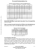
Characteristics. Table 4-2 lists some frequencies available from various combinations of
SYNCR bits with a reference frequency of 32.768-KHz.
Frees
cale Semiconductor,
I
Freescale Semiconductor, Inc.
For More Information On This Product,
Go to: www.freescale.com
nc...