
Typewriter User Manual


MOTOROLA MC68340 USER’S MANUAL 5- 97
Example 3 illustrates three different aspects of instruction time calculation:
1. The branch instruction does not attempt to prefetch beyond the minimum number of
words needed for itself.
2. The negative tail allows execution to begin sooner than a three-word pipeline would
allow.
3. There is a one-clock delay due to late arrival of the displacement at the CPU.
Only changes of flow require negative tail calculation, but the concept can be generalized
to any instruction—only two words are required to be in the pipeline, but up to three words
may be present. When there is an opportunity for an extra prefetch, it is made. A prefetch
to replace an instruction can begin ahead of the instruction, resulting in a faster processor.
5.7.3 Instruction Timing Tables
The following assumptions apply to the times shown in the subsequent tables.
—A 16-bit data bus is used for all memory accesses.
—Memory access times are based on two clock bus cycles with no wait states.
—The instruction pipeline is full at the beginning of the instruction and is refilled by
the end of the instruction.
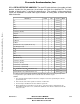
Three values are listed for each instruction and addressing mode:
Head: The number of cycles available at the beginning of an instruction to complete a
previous instruction write or to perform a prefetch.
Tail: The number of cycles an instruction uses to complete a write.
Cycles: Four numbers per entry, three contained in parentheses. The outer number is the
minimum number of cycles required for the instruction to complete. Numbers
within the parentheses represent the number of bus accesses performed by the
instruction. The first number is the number of operand read accesses performed
by the instruction. The second number is the number of instruction fetches
performed by the instruction, including all prefetches that keep the instruction and
the instruction pipeline filled. The third number is the number of write accesses
performed by the instruction.
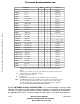
As an example, consider an ADD.L (12, A3, D7.W ∗ 4), D2 instruction.
Paragraph 5.7.3.5 Arithmetic/Logic Instructions shows that the instruction has a head =
0, a tail = 0, and cycles = 2 (0/1/0). However, in indexed, address register indirect
addressing mode, additional time is required to fetch the EA. Paragraph 5.7.3.1 Fetch
Effective Address gives addressing mode data. For (d
8
, An, Xn.Sz ∗ Scale), head = 4,
tail = 2, cycles = 8 (2/1/0). Because this example is for a long access and the fetch EA
table lists data for word accesses, add two clocks to the tail and to the number of cycles
(“X” in table notation) to obtain head = 4, tail = 4, cycles = 10 (2/1/0).
Assuming that no trailing write exists from the previous instruction, EA calculation requires
six clocks. Replacement fetch for the EA occurs during these six clocks, leaving a head of
Frees
cale Semiconductor,
I
Freescale Semiconductor, Inc.
For More Information On This Product,
Go to: www.freescale.com
nc...