
Typewriter User Manual


MOTOROLA MC68340 USER’S MANUAL 5-107
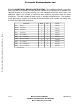
5.7.3.8 SINGLE OPERAND INSTRUCTIONS. The single operand instruction table
indicates the number of clock periods needed for the processor to perform the specified
operation using the specified addressing mode. The total number of clock cycles is
outside the parentheses. The numbers inside parentheses (r/p/w) are included in the total
clock cycle number. All timing data assumes two-clock reads and writes.
Instruction Head Tail Cycles
CLR Dn
0 0 2(0/1/0)
CLR 〈CEA〉
0 2 4(0/1/x)
NEG Dn
0 0 2(0/1/0)
NEG 〈FEA〉
0 3 5(0/1/x)
NEGX Dn
0 0 2(0/1/0)
NEGX 〈FEA〉
0 3 5(0/1/x)
NOT Dn
0 0 2(0/1/0)
NOT 〈FEA〉
0 3 5(0/1/x)
EXT Dn
0 0 2(0/1/0)
NBCD Dn
2 0 4(0/1/0)
NBCD 〈FEA〉
0 2 6(0/1/1)
Scc Dn
2 0 4(0/1/0)
Scc 〈CEA〉
2 2 6(0/1/1)
TAS Dn
4 0 6(0/1/0)
TAS 〈CEA〉
1 0 10(0/1/1)
TST 〈FEA〉
0 0 2(0/1/0)
X = There is one bus cycle for byte and word operands and two bus cycles for long-word
operands. For long-word bus cycles, add two clocks to the tail and to the number of
cycles.
Frees
cale Semiconductor,
I
Freescale Semiconductor, Inc.
For More Information On This Product,
Go to: www.freescale.com
nc...