
Typewriter User Manual


8- 14 MC68340 USER’S MANUAL MOTOROLA
f
f
f
9
START
C
OUNTING
ENABLE
STOP
C
OUNTING
NO EFFECT
MODEx Bits in Control Register = 101
TGE Bit of Control Register = 1
TGATE
COUNTER
CLOC
K
0
f
f
f
f
f
f
f
f
f
f
f
f
f
e
d
c
f
f
f
b
COUNTER
f
f
f
a
f
f
f
9
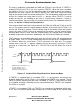
PERIOD MEASURED
Figure 8-9. Period Measurement Mode
If the counter counts down to the value stored in the COM register, the COM and TC bits
in the SR are set. If the counter counts down to $0000, a timeout is detected. This sets the
SR TO bit, and clears the SR COM bit. At timeout, the next falling edge of the counter
clock reloads the counter with $FFFF. TOUTx transitions at timeout or is disabled as
programmed by the OCx bits of the CR, and the OUT bit in the SR reflects the level on
TOUTx.
To determine the number of cycles counted, the value in the CNTR must be read,
inverted, and incremented by 1 (the first count is $FFFF which, in effect, includes a count
of zero). The counter counts in a true 2
16
fashion. For measuring pulses of even greater
duration, the value in the POx bits in the SR are readable and can be thought of as an
extension of the least significant bits in the CNTR.
NOTE
Once the timer has been enabled, do not clear the SR TG bit
until the pulse has been measured and
TGATE≈ has been
negated.
8.3.7 Event Count
This mode is used to count events by interpreting the falling edges of the counter clock as
events (see Figure 8-10). These events may be external or internal to the chip—for
example, counting the number of system clock cycles required to execute a sequence of
instructions. As another example, by connecting
AS to TINx, the number of bus cycles to
complete a sequence of instructions could be counted. This mode can be selected by
programming the CR MODEx bits to 110.
Frees
cale Semiconductor,
I
Freescale Semiconductor, Inc.
For More Information On This Product,
Go to: www.freescale.com
nc...