
Typewriter User Manual


MOTOROLA MC68340 USER’S MANUAL 9- 3
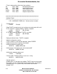
TEST LOGIC
RESET
RUN-TEST/IDLE
SELECT-DR_SCAN
CAPTURE-DR
SELECT-IR_SCAN
CAPTURE-IR
SHIFT-DR
SHIFT-IR
EXIT1-DR
EXIT1-IR
PAUSE-DR
PAUSE-IR
EXIT2-DR
UPDATE-DR
EXIT2-IR
UPDATE -IR
1
0
1
1
0
1
0
0
1
0
1
0
0
1
1
1
0
0
1
0
1
1
1
0
1
1
0
0
0
0
0
Figure 9-2. TAP Controller State Machine
9.3 BOUNDARY SCAN REGISTER
The MC68340 IEEE 1149.1 implementation has a 132-bit boundary scan register. This
register contains bits for all device signal and clock pins and associated control signals.
The XTAL, X2, and XFC pins are associated with analog signals and are not included in
the boundary scan register.
All MC68340 bidirectional pins, except the open-drain I/O pins (
DONE1, DONE2, HALT,
and RESET
), have a single register bit for pin data and an associated control bit in the
boundary scan register. All open drain I/O pins have two register bits, input and output, for
pin data and no associated control bit. To ensure proper operation, the open-drain pins
require external pullups. Twenty-three control bits in the boundary scan register define the
output enable signal for associated groups of bidirectional and three-state pins. The
control bits and their bit positions are listed in Table 9-1.
Frees
cale Semiconductor,
I
Freescale Semiconductor, Inc.
For More Information On This Product,
Go to: www.freescale.com
nc...