
Typewriter User Manual


MOTOROLA MC68340 USER’S MANUAL 3- 5
3.1.7.2 BUS ERROR (BERR). This signal is also a bus cycle termination indicator and
can be used in the absence of
DSACK≈ to indicate a bus error condition. BERR can also
be asserted in conjunction with
DSACK≈ to indicate a bus error condition, provided it
meets the appropriate timing described in this section and in Section 11 Electrical
Characteristics. Additionally,
BERR and HALT can be asserted together to indicate a
retry termination. Refer to 3.5 Bus Exception Control Cycles for additional information
on the use of these signals.
The internal bus monitor can be used to generate an internal bus error signal for internal
and internal-to-external transfers. If the bus cycles of an external bus master are to be
monitored, external
BERR generation must be provided since the internal bus error
monitor has no information about transfers initiated by an external bus master.
3.1.7.3 AUTOVECTOR (
AVEC).This signal can be used to terminate interrupt
acknowledge cycles, indicating that the MC68340 should internally generate a vector
(autovector) number to locate an interrupt handler routine.
AVEC can be generated either
externally or internally by the SIM40 (see Section 4 System Integration Module for
additional information).
AVEC is ignored during all other bus cycles.
3.2 DATA TRANSFER MECHANISM
The MC68340 supports byte, word, and long-word operands, allowing access to 8- and
16-bit data ports through the use of asynchronous cycles controlled by
DSACK1 and
DSACK0. The MC68340 also supports byte, word, and long-word operands, allowing
access to 8- and 16-bit data ports through the use of synchronous cycles controlled by the
fast termination capability of the SIM40.
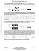
3.2.1 Dynamic Bus Sizing
The MC68340 dynamically interprets the port size of the addressed device during each
bus cycle, allowing operand transfers to or from 8- and 16-bit ports. During an operand
transfer cycle, the slave device signals its port size (byte or word) and indicates
completion of the bus cycle to the MC68340 through the use of the
DSACK≈ inputs. Refer
to Table 3-3 for
DSACK≈ encoding.
Table 3-3.
DSACK≈ Encoding
DSACK1 DSACK0 Result
1
(Negated)
1
(Negated) Insert Wait States in Current Bus Cycle
1
(Negated)
0
(Asserted) Complete Cycle—Data Bus Port Size Is 8 Bits
0
(Asserted)
1
(Negated) Complete Cycle—Data Bus Port Size Is 16 Bits
0
(Asserted)
0
(Asserted)
Reserved—Defaults to 16-Bit Port Size Can Be
Used for 32-Bit DMA cycles
Frees
cale Semiconductor,
I
Freescale Semiconductor, Inc.
For More Information On This Product,
Go to: www.freescale.com
nc...