
Typewriter User Manual


3- 14 MC68340 USER’S MANUAL MOTOROLA
3.2.4 Bus Operation
The MC68340 bus is asynchronous, allowing external devices connected to the bus to
operate at clock frequencies different from the clock for the MC68340. Bus operation uses
the handshake lines (
AS, DS, DSACK1/DSACK0, BERR, and HALT) to control data
transfers.
AS signals a valid address on the address bus, and DS is used as a condition
for valid data on a write cycle. Decoding the SIZx outputs and lower address line A0
provides strobes that select the active portion of the data bus. The slave device (memory
or peripheral) responds by placing the requested data on the correct portion of the data
bus for a read cycle or by latching the data on a write cycle; the slave asserts the
DSACK1/DSACK0 combination that corresponds to the port size to terminate the cycle.
Alternatively, the SIM40 can be programmed to assert the
DSACK1/DSACK0 combination
internally and respond for the slave. If no slave responds or the access is invalid, external
control logic may assert
BERR to abort the bus cycle or BERR with HALT to retry the bus
cycle.
DSACK≈ can be asserted before the data from a slave device is valid on a read cycle.
The length of time that
DSACK≈ may precede data must not exceed a specified value in
any asynchronous system to ensure that valid data is latched into the MC68340. (See
Section 11 Electrical Characteristics for timing parameters.) Note that no maximum
time is specified from the assertion of
AS to the assertion of DSACK≈. Although the
MC68340 can transfer data in a minimum of three clock cycles when the cycle is
terminated with
DSACK≈, the MC68340 inserts wait cycles in clock-period increments
until
DSACK≈ is recognized. BERR and/or HALT can be asserted after DSACK≈ is
asserted.
BERR and or HALT must be asserted within the time specified after DSACK≈ is
asserted in any asynchronous system. If this maximum delay time is violated, the
MC68340 may exhibit erratic behavior.
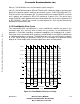
3.2.5 Synchronous Operation with DSACK≈
Although cycles terminated with DSACK≈ are classified as asynchronous, cycles
terminated with
DSACK≈ can also operate synchronously in that signals are interpreted
relative to clock edges. The devices that use these cycles must synchronize the response
to the MC68340 clock (CLKOUT) to be synchronous. Since the devices terminate bus
cycles with
DSACK≈, the dynamic bus sizing capabilities of the MC68340 are available.
The minimum cycle time for these cycles is also three clocks. To support systems that use
the system clock to generate
DSACK≈ and other asynchronous inputs, the asynchronous
input setup time and the asynchronous input hold time are given. If the setup and hold
times are met for the assertion or negation of a signal such as
DSACK≈, the MC68340 is
guaranteed to recognize that signal level on that specific falling edge of the system clock.
If the assertion of
DSACK≈ is recognized on a particular falling edge of the clock, valid
data is latched into the MC68340 (for a read cycle) on the next falling clock edge if the
data meets the data setup time. In this case, the parameter for asynchronous operation
can be ignored. The timing parameters are described in Section 11 Electrical
Characteristics.
Frees
cale Semiconductor,
I
Freescale Semiconductor, Inc.
For More Information On This Product,
Go to: www.freescale.com
nc...