
Typewriter User Manual


3- 22 MC68340 USER’S MANUAL MOTOROLA
3.4.1 Breakpoint Acknowledge Cycle
The breakpoint acknowledge cycle allows external hardware to insert an instruction
directly into the instruction pipeline as the program executes. The breakpoint acknowledge
cycle is generated by the execution of a breakpoint instruction (BKPT) or the assertion of
the
BKPT pin. The T-bit state (shown in Figure 3-10) differentiates a software breakpoint
cycle (T = 0) from a hardware breakpoint cycle (T = 1).
When a BKPT instruction is executed (software breakpoint), the MC68340 performs a
word read from CPU space, type 0, at an address corresponding to the breakpoint number
(bits [2–0] of the BKPT opcode) on A4–A2, and the T-bit (A1) is cleared. If this bus cycle is
terminated with
BERR (i.e., no instruction word is available), the MC68340 then performs
illegal instruction exception processing. If the bus cycle is terminated by
DSACK≈, the
MC68340 uses the data on D15–D0 (for 16-bit ports) or two reads from D15–D8 (for 8-bit
ports) to replace the BKPT instruction in the internal instruction pipeline and then begins
execution of that instruction.
When the CPU32 acknowledges a
BKPT pin assertion (hardware breakpoint) with
background mode disabled, the CPU32 performs a word read from CPU space, type 0, at
an address corresponding to all ones on A4–A2 (BKPT#7), and the T-bit (A1) is set. If this
bus cycle is terminated by
BERR, the MC68340 performs hardware breakpoint exception
processing. If this bus cycle is terminated by
DSACK≈, the MC68340 ignores data on the
data bus and continues execution of the next instruction.
NOTE
The
BKPT pin is sampled on the same clock phase as data
and is latched with data as it enters the CPU32 pipeline. If
BKPT is asserted for only one bus cycle and a pipeline flush
occurs before
BKPT is detected by the CPU32, BKPT is
ignored. To ensure detection of
BKPT by the CPU32, BKPT
can be asserted until a breakpoint acknowledge cycle is
recognized.
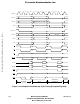
The breakpoint operation flowchart is shown in Figure 3-11. Figures 3-12 and 3-13 show
the timing diagrams for the breakpoint acknowledge cycle with instruction opcodes
supplied on the cycle and with an exception signaled, respectively.
Frees
cale Semiconductor,
I
Freescale Semiconductor, Inc.
For More Information On This Product,
Go to: www.freescale.com
nc...