
Typewriter User Manual


MOTOROLA MC68340 USER’S MANUAL 3- 27
3.4.3 Module Base Address Register Access
All internal module registers, including the SIM40, occupy a single 4-Kbyte block that is
relocatable along 4-Kbyte boundaries. The location is fixed by writing the desired base
address of the SIM40 block to the module base address register using the MOVES
instruction. The module base address register is only accessible in CPU space at address
$0003FF00. The SFC or DFC register must indicate CPU space (FC3–FC0 = $7), using
the MOVEC instruction, before accessing the module base address register. Refer to
Section 4 System Integration Module for additional information on the module base
address register.
3.4.4 Interrupt Acknowledge Bus Cycles
The CPU32 makes an interrupt pending in three cases. The first case occurs when a
peripheral device signals the CPU32 (with
IRQ7–IRQ1) that the device requires service
and the internally synchronized value on these signals indicates a higher priority than the
interrupt mask in the status register. The second case occurs when a transition has
occurred in the case of a level 7 interrupt. A recognized level 7 interrupt must be removed
for one clock cycle before a second level 7 can be recognized. The third case occurs if,
upon returning from servicing a level 7 interrupt, the request level stays at 7 and the
processor mask level changes from 7 to a lower level, a second level 7 is recognized. The
CPU32 takes an interrupt exception for a pending interrupt within one instruction boundary
(after processing any other pending exception with a higher priority). The following
paragraphs describe the types of interrupt acknowledge bus cycles that can be executed
as part of interrupt exception processing.
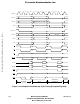
3.4.4.1 INTERRUPT ACKNOWLEDGE CYCLE—TERMINATED NORMALLY. When the
CPU32 processes an interrupt exception, it performs an interrupt acknowledge cycle to
obtain the number of the vector that contains the starting location of the interrupt service
routine. Some interrupting devices have programmable vector registers that contain the
interrupt vectors for the routines they use. The following paragraphs describe the interrupt
acknowledge cycle for these devices. Other interrupting conditions or devices that cannot
supply a vector number will use the autovector cycle described in 3.4.4.2 Autovector
Interrupt Acknowledge Cycle.
Frees
cale Semiconductor,
I
Freescale Semiconductor, Inc.
For More Information On This Product,
Go to: www.freescale.com
nc...